




.svg&w=240)


















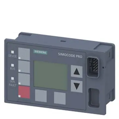
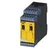
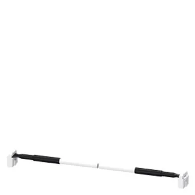
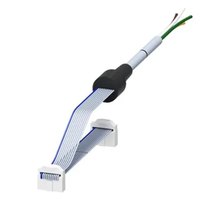
Siemens 3UF7320-1AB00-0
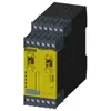
Fail-safe digital module DM-F local
- MPN
- 3UF7320-1AB00-0
Price and lead time confirmed within 1 business day
Request a Quote
- 12-month warranty (new) · 3-month (used/refurbished)
- 30-day returns, no restocking fee on unused parts
- Ships via



What is the Siemens 3UF7320-1AB00-0?
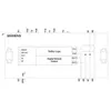
fail-safe digital module DM-F local, for fail-safe shutdown via hardware signal Us: 24 V DC 2 relay enabling circuits, 2 relay outputs, safety function can be set via DIP switch, maximum achievable SIL IEC 61508: 3, maximum achievable PL ISO 13849-1: E
Specifications
General
| product brand name | SIMOCODE |
| product designation | Fail-safe digital module |
| design of the product | for emergency off and safety doors |
| product type designation | DM-FL |
General technical data
| product function — EMERGENCY OFF function | Yes |
| product function — automatic start | Yes |
| product function — light barrier monitoring | Yes |
| product function — light array monitoring | Yes |
| product function — protective door monitoring | Yes |
| product function — magnetically operated switch monitoring NC-NO | Yes |
| product function — magnetically operated switch monitoring NC-NC | Yes |
| product function — pressure-sensitive mat monitoring | Yes |
| product function — monitored start-up | Yes |
| product component — input for thermistor connection | No |
| product component — digital input | Yes |
| product component — input for analog temperature sensors | No |
| product component — input for ground fault detection | No |
| product component — relay output | Yes |
| consumed active power | 3 W |
| insulation voltage with degree of pollution 3 at AC rated value | 300 V |
| surge voltage resistance rated value | 4 000 V |
| shock resistance according to IEC 60068-2-27 | 15 g / 11 ms |
| vibration resistance according to IEC 60068-2-6 | 1 ... 6 Hz: 15 mm, 6 ... 500 Hz: 2 g |
| operating frequency maximum | 360 1/y |
| switching capacity current of the NO contacts of the relay outputs at AC-15 — at 24 V | 3 A |
| switching capacity current of the NO contacts of the relay outputs at AC-15 — at 120 V | 3 A |
| switching capacity current of the NO contacts of the relay outputs at AC-15 — at 240 V | 1.5 A |
| switching capacity current of the NO contacts of the relay outputs at DC-13 — at 24 V | 4 A |
| switching capacity current of the NO contacts of the relay outputs at DC-13 — at 60 V | 0.55 A |
| switching capacity current of the NO contacts of the relay outputs at DC-13 — at 125 V | 0.22 A |
| switching capacity current of the NO contacts of the relay outputs at DC-13 — at 250 V | 0.11 A |
| switching capacity current of relay enabling circuits at AC-15 — at 24 V | 3 A |
| switching capacity current of relay enabling circuits at AC-15 — at 120 V | 3 A |
| switching capacity current of relay enabling circuits at AC-15 — at 240 V | 1.5 A |
| switching capacity current of relay enabling circuits at DC-13 — at 24 V | 4 A |
| switching capacity current of relay enabling circuits at DC-13 — at 60 V | 0.55 A |
| switching capacity current of relay enabling circuits at DC-13 — at 125 V | 0.22 A |
| switching capacity current of relay enabling circuits at DC-13 — at 250 V | 0.11 A |
| mechanical service life (operating cycles) typical | 10 000 000 |
| electrical endurance (operating cycles) typical | 100 000 |
| buffering time in the event of power failure | 60 ms |
| recovery time — after power failure typical | 8 s |
| recovery time — after opening of the safety circuits typical | 250 ms |
| make time with automatic start — typical | 50 ms |
| make time with automatic start — maximum | 100 ms |
| make time with automatic start — at DC maximum | 100 ms |
| make time with automatic start — after power failure typical | 8 000 ms |
| make time with automatic start — after power failure maximum | 8 200 ms |
| backslide delay time after opening of the safety circuits typical | 50 ms |
| backslide delay time in the event of power failure — typical | 40 ms |
| backslide delay time in the event of power failure — maximum | 80 ms |
| reference code according to IEC 81346-2 | F |
| reference code according to IEC 81346-2:2019 | F |
| type of input characteristic | Type 2 in accordance with EN 61131-2 |
| Substance Prohibitance (day/month/year) | 05/01/2012 |
| SVHC substance name | Lead CAS-No. 7439-92-1 Lead monoxide (lead oxide) CAS-No. 1317-36-8 2-methyl-1-(4-methylthiophenyl)-2-morpholinopropan-1-one CAS-No. 71868-10-5 Melamine CAS-No. 108-78-1 6,6'-di-tert-butyl-2,2'-methylenedi-p-cresol CAS-No. 119-47-1 |
| Net Weight | 0.319 kg |
Electromagnetic compatibility
| EMC emitted interference according to IEC 60947-1 | class A |
| EMC immunity according to IEC 60947-1 | corresponds to degree of severity 3 |
| conducted interference — due to burst according to IEC 61000-4-4 | 2 kV network connection / 1 kV control connection |
| conducted interference — due to conductor-earth surge according to IEC 61000-4-5 | 1 kV |
| conducted interference — due to conductor-conductor surge according to IEC 61000-4-5 | 0.5 kV |
| conducted interference — due to high-frequency radiation according to IEC 61000-4-6 | 10 V |
| field-based interference according to IEC 61000-4-3 | 10 V/m |
| electrostatic discharge according to IEC 61000-4-2 | 6 kV contact discharge / 8 kV air discharge |
| conducted HF interference emissions according to CISPR11 | corresponds to degree of severity A |
| field-bound HF interference emission according to CISPR11 | corresponds to degree of severity A |
Inputs/ Outputs
| product function — parameterizable inputs | Yes |
| product function — parameterizable outputs | Yes |
| number of inputs | 5 |
| design of input — cascading input/functional switching | Yes |
| design of input — feedback input | Yes |
| design of input — start input | Yes |
| pulse duration — of the sensor input minimum | 30 ms |
| pulse duration — of the ON pushbutton input minimum | 0.2 s |
| pulse duration — of the cascading input minimum | 0.2 s |
| number of digital inputs | 0 |
| number of digital inputs — with a common reference potential | 4 |
| digital input version — type 1 acc. to IEC 61131 | No |
| digital input version — type 2 acc. to IEC 61131 | Yes |
| number of analog inputs | 0 |
| number of sensor inputs — 1-channel or 2-channel | 1 |
| number of sensor inputs — 2-channel | 1 |
| number of outputs | 2 |
| number of semiconductor outputs | 0 |
| number of outputs as contact-affected switching element — as NO contact safety-related instantaneous contact | 2 |
| number of analog outputs | 0 |
| switching behavior | monostable |
| property of contacts of the relay outputs | Fail-safe NO contacts |
| wire length for digital signals maximum | 1 500 m |
Product Function
| suitability for use — position switch monitoring | Yes |
| suitability for use — EMERGENCY-OFF circuit monitoring | Yes |
| suitability for use — valve monitoring | No |
| suitability for use — opto-electronic protection device monitoring | Yes |
| suitability for use — tactile sensor monitoring | No |
| suitability for use — magnetically operated switch monitoring | Yes |
| suitability for use — proximity switch monitoring | No |
| suitability for use — safety-related circuits | Yes |
Installation/ mounting/ dimensions
| mounting position | any |
| fastening method | screw and snap-on mounting |
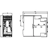
| height | 106 mm |
| width | 45 mm |
| depth | 124 mm |
| required spacing — top | 40 mm |
| required spacing — bottom | 40 mm |
| required spacing — left | 0 mm |
| required spacing — right | 0 mm |
Connections/ Terminals
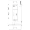
| product component removable terminal for auxiliary and control circuit | Yes |
| type of electrical connection for auxiliary and control circuit | screw-type terminals |
| type of connectable conductor cross-sections — solid | 1x (0.5 ... 4.0mm²), 2x (0.5 ... 2.5 mm²) |
| type of connectable conductor cross-sections — finely stranded with core end processing | 1x (0.5 ... 2.5 mm²), 2x (0.5 ... 1.5 mm²) |
| type of connectable conductor cross-sections — for AWG cables solid | 1x (20 ... 12), 2x (20 ... 14) |
| type of connectable conductor cross-sections — for AWG cables stranded | 1x (20 ... 14), 2x (20 ... 16) |
| tightening torque with screw-type terminals | 0.8 ... 1.2 N·m |
| tightening torque [lbf·in] with screw-type terminals | 7 ... 10.3 lbf·in |
Ambient conditions
| installation altitude at height above sea level — 1 maximum | 2 000 m |
| installation altitude at height above sea level — 2 maximum | 3 000 m; max. +50 °C (no protective separation) |
| installation altitude at height above sea level — 3 maximum | 4 000 m; max. +40 °C (no protective separation) |
| ambient temperature — during operation | -25 ... +60 °C |
| ambient temperature — during storage | -40 ... +80 °C |
| ambient temperature — during transport | -40 ... +80 °C |
| environmental category — during operation according to IEC 60721 | 3K6 (no formation of ice, no condensation, relative humidity 10 ... 95%), 3C3 (no salt mist), 3S2 (sand must not get into the devices), 3M6 |
| environmental category — during storage according to IEC 60721 | 1K6 (no condensation, relative humidity 10 ... 95%), 1C2 (no salt mist), 1S2 (sand must not get into the devices), 1M4 |
| environmental category — during transport according to IEC 60721 | 2K2, 2C1, 2S1, 2M2 |
| relative humidity during operation | 5 ... 95 % |
| contact rating of auxiliary contacts according to UL | B300 / R300 |
Short-circuit protection
| design of the fuse link for short-circuit protection of relay enabling circuits required | gL/gG: 4 A |
Safety related data
| product function suitable for safety function | Yes |
| safe state | Safety outputs switched off |
| diagnostics test interval by internal test function maximum | 28 800 s |
| stop category according to IEC 60204-1 | 0 |
| failure rate [FIT] at rate of recognizable hazardous failures (λdd) | 868 FIT |
| failure rate [FIT] at rate of non-recognizable hazardous failures (λdu) | 7 FIT |
| average diagnostic coverage level (DCavg) — at single-channel evaluation | 90 % |
| average diagnostic coverage level (DCavg) — at 2-channel evaluation | 99 % |
| Safety Integrity Level (SIL) — at single-channel evaluation according to IEC 62061 | 1 |
| Safety Integrity Level (SIL) — at 2-channel evaluation according to IEC 62061 | 3 |
| performance level (PL) — at single-channel evaluation according to ISO 13849-1 | d |
| performance level (PL) — at 2-channel evaluation according to ISO 13849-1 | e |
| category — at single-channel evaluation according to ISO 13849-1 | 2 |
| category — at 2-channel evaluation according to ISO 13849-1 | 4 |
| Safety Integrity Level (SIL) — at single-channel evaluation according to IEC 61508 | 1 |
| Safety Integrity Level (SIL) — at 2-channel evaluation according to IEC 61508 | 3 |
| safety device type according to IEC 61508-2 | Type B |
| PFDavg with low demand rate — at single-channel evaluation according to IEC 61508 | 0.00065 |
| PFDavg with low demand rate — at 2-channel evaluation according to IEC 61508 | 2E-5 |
| Safe failure fraction (SFF) | 99 % |
| hardware fault tolerance — at single-channel evaluation according to IEC 61508 | 0 |
| hardware fault tolerance — at 2-channel evaluation according to IEC 61508 | 1 |
| T1 value for proof test interval or service life according to IEC 61508 | 20 a |
| touch protection against electrical shock | finger-safe |
ATEX
| certificate of suitability according to ATEX directive 2014/34/EU | BVS 06 ATEX F001 |
| explosion device group and category according to ATEX directive 2014/34/EU | II (2) G, II (2 ) D, I (M2) |
Galvanic isolation
| (electrically) protective separation according to IEC 60947-1 | All circuits in SIMOCODE pro are with protective separation, i.e. they are designed with doubled creepage paths and clearances. NOTICE: The information in the "Protective Separation" test report, No. 2668, must be observed. |
| design of the electrical isolation | Protective separation in accordance with IEC 60947-1 for all circuits, up to installation altitude of 2000 m |
Control circuit/ Control
| type of voltage of the control supply voltage | DC |
| control supply voltage at DC rated value | 24 V |
| operating range factor control supply voltage rated value at DC — initial value | 0.8 |
| operating range factor control supply voltage rated value at DC — full-scale value | 1.2 |
| inrush current peak — at 24 V | 8.3 A |
| duration of inrush current peak — at 24 V | 1 ms |
Downloads & documentation
Official documents from Siemens, downloaded directly from the manufacturer.
Data sheets & manuals
3UF7320-1AB00-0: frequently asked questions
When can 3UF7320-1AB00-0 be shipped?
3UF7320-1AB00-0 is sourced on request — request a quote and we'll confirm the exact availability and shipping timeline for this specific unit.
Can I pick up 3UF7320-1AB00-0 in person?
Local pickup from our Groningen, Netherlands warehouse may be possible — contact us before ordering to check availability and arrange a collection time.
Is express delivery available?
Yes — mention it when you request a quote for 3UF7320-1AB00-0 and we'll include express shipping options in our reply.
My factory is down and I need this urgently — can you help?
For a critical breakdown, contact us directly at +31 (0)50-7110348 or sales@partnerplc.com — we can look into same-day courier or dedicated taxi/hotshot delivery for 3UF7320-1AB00-0, subject to availability and destination.
More Siemens parts
Siemens 3UF7320-1AB00-0Price and lead time confirmed within 1 business day
Request a Quote