


Pepperl Fuchs LB7104A
Request a Quote



Quick facts
| Availability | Confirmed on request |
| Category | LB (Zone 2, Class I/Div. 2) |
| Lifecycle | active |
| Warranty | 12-month (new) · 3-month (used/refurbished) |
Shipping & availability
When can LB7104A be shipped?
LB7104A is sourced on request — request a quote and we'll confirm the exact availability and shipping timeline for this specific unit.
Can I pick up LB7104A in person?
Local pickup from our Groningen, Netherlands warehouse may be possible — contact us before ordering to check availability and arrange a collection time.
Is express delivery available?
Yes — mention it when you request a quote for LB7104A and we'll include express shipping options in our reply.
My factory is down and I need this urgently — can you help?
For a critical breakdown, contact us directly at +31 (0)50-7110348 or sales@partnerplc.com — we can look into same-day courier or dedicated taxi/hotshot delivery for LB7104A, subject to availability and destination.
Universal Input/Output (HART). 4-channel, Inputs Ex ia, Outputs Ex ia, Analog input, digital input,<br>analog output, digital output, Mounting in Zone 2, Class I/Div.2 or in the safe area. Occupied slots: 1. Connection: backplane bus. Rated voltage: 12 V DC , only in connection with the power supplies LB9***. Power dissipation: 2 W. Power consumption: 3 W. Connection: backplane bus. Interface: manufacturer-specific bus to standard com unit. Number of channels: 4. Suitable field devices: . Field devicepressure converterField device [2]flow converterField device [3]level converterField device [4]Temperature Converter: . Field device: pressure converter. Field device [2]: flow converter. Field device [3]: level converter. Field device [4]: Temperature Converter. Field device interface: . Connection2-wire transmitter: . Connection: 2-wire transmitter. Connection: terminals 1+, 2-; 3+, 4-; 5+, 6-; 7+, 8-. Transmitter supply voltage: min. 15 V at 20 mA ; 21.5 V at 4 mA. Input resistance: 15 Ω. Line fault detection: can be switched on/off for each channel via configuration tool , configurable via configuration tool. Short-circuitfactory setting: > 21 mA Can be parameterized in the range 0 ... 22 mAOpen-circuitfactory setting: < 3.6 mA Can be parameterized in the range 0 ... 22 mA: . Short-circuit: factory setting: > 21 mA Can be parameterized in the range 0 ... 22 mA. Open-circuit: factory setting: < 3.6 mA Can be parameterized in the range 0 ... 22 mA. HART communication: yes. HART secondary variable: yes. Number of channels: 4. Suitable field devices: . Field deviceProportional ValveField device [2]I/P convertersField device [3]on-site display: . Field device: Proportional Valve. Field device [2]: I/P converters. Field device [3]: on-site display. Connection: terminals 1+, 2-; 3+, 4-; 5+, 6-; 7+, 8-. Current: 0 ... 20 mA short-circuit protected. Line fault detection: can be switched on/off for each channel via configuration tool , configurable via configuration tool. Short-circuitfactory setting: < 50 Ω configurable between 0 ... 26 mAOpen-circuitdeviation of preset output value > 0.5 mA: . Short-circuit: factory setting: < 50 Ω configurable between 0 ... 26 mA. Open-circuit: deviation of preset output value > 0.5 mA. Load: max. 750 Ω at 20 mA. HART communication: yes. HART secondary variable: yes. Watchdog: output off 0.5 s after serious fault. Number of channels: 4. Sensor interface: . Connection [2]volt-free contact: . Connection [2]: volt-free contact. Connection: terminals 1+, 2-; 3+, 4-; 5+, 6-; 7+, 8-. Line fault detection: can be switched on/off for each channel via configuration tool. Connectionmechanical switch with additional resistors (see connection diagram)Short-circuit> 7 mAOpen-circuit< 0.1 mA: . Connection: mechanical switch with additional resistors (see connection diagram). Short-circuit: > 7 mA. Open-circuit: < 0.1 mA. Digital signals (active): . Switching point: ON> 2.1 mASwitching point: OFF< 1.2 mA: . Switching point: ON: > 2.1 mA. Switching point: OFF: < 1.2 mA. Number of channels: 4. Suitable field devices: . Field deviceSolenoid ValveField device [2]audible alarmField device [3]visual alarm: . Field device: Solenoid Valve. Field device [2]: audible alarm. Field device [3]: visual alarm. Connection: terminals 1+, 2-, 3+, 4-, 5+, 6-, 7+, 8-. Drive capability: 12 V / 22 mA. Internal resistor: 385 Ω. Current limit: 22 mA. Open loop voltage: min. 22.7 V. Line fault detection: can be switched on/off for each channel via configuration tool. Test current0.4 mAShort-circuit< 50 ΩOpen-circuit< 0.2 mA: . Test current: 0.4 mA. Short-circuit: < 50 Ω. Open-circuit: < 0.2 mA. Deviation: . After calibration0.1 % of the signal range at 20 °C (68 °F)Influence of ambient temperature0.1 %/10 K of the signal range: . After calibration: 0.1 % of the signal range at 20 °C (68 °F). Influence of ambient temperature: 0.1 %/10 K of the signal range. Refresh time: approx. 100 ms (4 channels). LED indication: Power LED (P) green: supply Diagnostic LED (I) red: module fault , red flashing: communication error , white: fixed parameter set (parameters from com unit are ignored) , white flashing: requests parameters from com unit Status LED (1-4) red: line fault (lead breakage or short circuit) , yellow: state of digital I/O (0/1) Configuration LED (AI, AO, DI, DO) white: selected channel mode. Coding: optional mechanical coding via front socket. Electromagnetic compatibility: . Directive 2014/30/EUEN 61326-1:2013: . Directive 2014/30/EU: EN 61326-1:2013. Electromagnetic compatibility: NE 21:2007. Degree of protection: IEC 60529:2000. Environmental test: EN 60068-2-14:2009. Shock resistance: EN 60068-2-27:2009. Vibration resistance: EN 60068-2-6:2008. Damaging gas: EN 60068-2-42:2003. Relative humidity: EN 60068-2-78:2001. Ambient temperature: -40 ... 60 °C (-40 ... 140 °F). Storage temperature: -40 ... 85 °C (-40 ... 185 °F). Relative humidity: 95 % non-condensing. Altitude: max. 2000 m. Shock resistance: shock type I, shock duration 11 ms, shock amplitude 15 g, number of shocks 18. Vibration resistance: frequency range 10 ... 150 Hz; transition frequency: 57.56 Hz, amplitude/acceleration ± 0.075 mm/1 g; 10 cyclesfrequency range 5 ... 100 Hz; transition frequency: 13.2 Hz amplitude/acceleration ± 1 mm/0.7 g; 90 minutes at each resonance. Damaging gas: designed for operation in environmental conditions acc. to ISA-S71.04-1985, severity level G3. Degree of protection: IP20 when mounted on backplane. Connection: removable front connector with screw flange (accessory)wiring connection via spring terminals (0.14 ... 1.5 mm2) or screw terminals (0.08 ... 1.5 mm2). Mass: approx. 100 g. Dimensions: . Height100 mmWidth16 mmDepth102 mm: . Height: 100 mm. Width: 16 mm. Depth: 102 mm. EU-type examination certificate: BVS 11 ATEX E 116 X. Marking II 3(1) G Ex nA [ia Ga] IIC T4 Gc[exsign] I (M1) [Ex ia Ma] I[exsign] II (1) D [Ex ia Da] IIIC: . Marking: II 3(1) G Ex nA [ia Ga] IIC T4 Gc[exsign] I (M1) [Ex ia Ma] I[exsign] II (1) D [Ex ia Da] IIIC. Input: . VoltageUo27 VCurrentIo87 mAPowerPo575 mW (linear characteristic): Uo. Voltage: 27 V. Current: 87 mA. Power: 575 mW (linear characteristic). Output: Ex ia. VoltageUo27 VCurrentIo87 mAPowerPo575 mW (linear characteristic)Internal capacitanceCi12 nFInternal inductanceLi0 mH: Uo. Voltage: 27 V. Current: 87 mA. Power: 575 mW (linear characteristic). Internal capacitance: 12 nF. Internal inductance: 0 mH. Galvanic isolation: . Rated voltageUm250 V field circuits to control and supply circuitsInput/power supply, internal bussafe electrical isolation acc. to EN 60079-11, voltage peak value 375 VOutput/power supply, internal bussafe electrical isolation acc. to EN 60079-11, voltage peak value 375 V: Um. Rated voltage: 250 V field circuits to control and supply circuits. Input/power supply, internal bus: safe electrical isolation acc. to EN 60079-11, voltage peak value 375 V. Output/power supply, internal bus: safe electrical isolation acc. to EN 60079-11, voltage peak value 375 V. Directive conformity: . Directive 2014/34/EUEN IEC 60079-0:2018+AC:2020 EN 60079-11:2012 EN 60079-15:2010: . Directive 2014/34/EU: EN IEC 60079-0:2018+AC:2020 EN 60079-11:2012 EN 60079-15:2010. ATEX approval: BVS 11 ATEX E 116X. UL approval: E106378. IECEx approval: . IECEx certificateIECEx BVS 11.0068XIECEx markingEx nA [ia Ga] IIC T4 Gc [Ex ia Da] IIIC [Ex ia Ma] I: . IECEx certificate: IECEx BVS 11.0068X. IECEx marking: Ex nA [ia Ga] IIC T4 Gc [Ex ia Da] IIIC [Ex ia Ma] I. System information: The module has to be mounted in appropriate backplanes (LB9***) in Zone 2 or outside hazardous areas. Here, observe the corresponding declaration of conformity. For use in hazardous areas (e. g. Zone 2, Zone 22 or Div. 2) the module must be installed in an appropriate enclosure.. Supplementary information: EC-Type Examination Certificate, Statement of Conformity, Declaration of Conformity, Attestation of Conformity and instructions have to be observed where applicable. For information see www.pepperl-fuchs.com.
Specifications
Slots
| Occupied slots | 1 |
Supply
| Connection | backplane bus |
| Rated voltage | 12 V DC , only in connection with the power supplies LB9*** Ur |
| Power dissipation | 2 W |
| Power consumption | 3 W |
Internal bus
| Connection | backplane bus |
| Interface | manufacturer-specific bus to standard com unit |
Analog input
| Number of channels | 4 |
| Suitable field devices | |
| Field devicepressure converterField device [2]flow converterField device [3]level converterField device [4]Temperature Converter | Field device |
| Field device | pressure converter |
| Field device [2] | flow converter |
| Field device [3] | level converter |
| Field device [4] | Temperature Converter |
| Field device interface | |
| Connection2-wire transmitter | Connection |
| Connection | 2-wire transmitter |
| Connection | terminals 1+, 2-; 3+, 4-; 5+, 6-; 7+, 8- |
| Transmitter supply voltage | min. 15 V at 20 mA ; 21.5 V at 4 mA |
| Input resistance | 15 Ω |
| Line fault detection | can be switched on/off for each channel via configuration tool , configurable via configuration tool |
| Short-circuitfactory setting: > 21 mA Can be parameterized in the range 0 ... 22 mAOpen-circuitfactory setting: < 3.6 mA Can be parameterized in the range 0 ... 22 mA | Short-circuit |
| Short-circuit | factory setting: > 21 mA Can be parameterized in the range 0 ... 22 mA |
| Open-circuit | factory setting: < 3.6 mA Can be parameterized in the range 0 ... 22 mA |
| HART communication | yes |
| HART secondary variable | yes |
Analog output
| Number of channels | 4 |
| Suitable field devices | |
| Field deviceProportional ValveField device [2]I/P convertersField device [3]on-site display | Field device |
| Field device | Proportional Valve |
| Field device [2] | I/P converters |
| Field device [3] | on-site display |
| Connection | terminals 1+, 2-; 3+, 4-; 5+, 6-; 7+, 8- |
| Current | 0 ... 20 mA short-circuit protected |
| Line fault detection | can be switched on/off for each channel via configuration tool , configurable via configuration tool |
| Short-circuitfactory setting: < 50 Ω configurable between 0 ... 26 mAOpen-circuitdeviation of preset output value > 0.5 mA | Short-circuit |
| Short-circuit | factory setting: < 50 Ω configurable between 0 ... 26 mA |
| Open-circuit | deviation of preset output value > 0.5 mA |
| Load | max. 750 Ω at 20 mA |
| HART communication | yes |
| HART secondary variable | yes |
| Watchdog | output off 0.5 s after serious fault |
Digital input
| Number of channels | 4 |
| Sensor interface | |
| Connection [2]volt-free contact | Connection [2] |
| Connection [2] | volt-free contact |
| Connection | terminals 1+, 2-; 3+, 4-; 5+, 6-; 7+, 8- |
| Line fault detection | can be switched on/off for each channel via configuration tool |
| Connectionmechanical switch with additional resistors (see connection diagram)Short-circuit> 7 mAOpen-circuit< 0.1 mA | Connection |
| Connection | mechanical switch with additional resistors (see connection diagram) |
| Short-circuit | > 7 mA |
| Open-circuit | < 0.1 mA |
| Digital signals (active) | |
| Switching point: ON> 2.1 mASwitching point: OFF< 1.2 mA | Switching point: ON |
| Switching point: ON | > 2.1 mA |
| Switching point: OFF | < 1.2 mA |
Digital output
| Number of channels | 4 |
| Suitable field devices | |
| Field deviceSolenoid ValveField device [2]audible alarmField device [3]visual alarm | Field device |
| Field device | Solenoid Valve |
| Field device [2] | audible alarm |
| Field device [3] | visual alarm |
| Connection | terminals 1+, 2-, 3+, 4-, 5+, 6-, 7+, 8- |
| Drive capability | 12 V / 22 mA |
| Internal resistor | 385 Ω Ri |
| Current limit | 22 mA Imax |
| Open loop voltage | min. 22.7 V Us |
| Line fault detection | can be switched on/off for each channel via configuration tool |
| Test current0.4 mAShort-circuit< 50 ΩOpen-circuit< 0.2 mA | Test current |
| Test current | 0.4 mA |
| Short-circuit | < 50 Ω |
| Open-circuit | < 0.2 mA |
Transfer characteristics
| Deviation | |
| After calibration0.1 % of the signal range at 20 °C (68 °F)Influence of ambient temperature0.1 %/10 K of the signal range | After calibration |
| After calibration | 0.1 % of the signal range at 20 °C (68 °F) |
| Influence of ambient temperature | 0.1 %/10 K of the signal range |
| Refresh time | approx. 100 ms (4 channels) |
Indicators/settings
| LED indication | Power LED (P) green: supply Diagnostic LED (I) red: module fault , red flashing: communication error , white: fixed parameter set (parameters from com unit are ignored) , white flashing: requests parameters from com unit Status LED (1-4) red: line fault (lead breakage or short circuit) , yellow: state of digital I/O (0/1) Configuration LED (AI, AO, DI, DO) white: selected channel mode |
| Coding | optional mechanical coding via front socket |
Directive conformity
| Electromagnetic compatibility | |
| Directive 2014/30/EUEN 61326-1:2013 | Directive 2014/30/EU |
| Directive 2014/30/EU | EN 61326-1:2013 |
Conformity
| Electromagnetic compatibility | NE 21:2007 |
| Degree of protection | IEC 60529:2000 |
| Environmental test | EN 60068-2-14:2009 |
| Shock resistance | EN 60068-2-27:2009 |
| Vibration resistance | EN 60068-2-6:2008 |
| Damaging gas | EN 60068-2-42:2003 |
| Relative humidity | EN 60068-2-78:2001 |
Ambient conditions
| Ambient temperature | -40 ... 60 °C (-40 ... 140 °F) |
| Storage temperature | -40 ... 85 °C (-40 ... 185 °F) |
| Relative humidity | 95 % non-condensing |
| Altitude | max. 2000 m |
| Shock resistance | shock type I, shock duration 11 ms, shock amplitude 15 g, number of shocks 18 |
| Vibration resistance | frequency range 10 ... 150 Hz; transition frequency: 57.56 Hz, amplitude/acceleration ± 0.075 mm/1 g; 10 cyclesfrequency range 5 ... 100 Hz; transition frequency: 13.2 Hz amplitude/acceleration ± 1 mm/0.7 g; 90 minutes at each resonance |
| Damaging gas | designed for operation in environmental conditions acc. to ISA-S71.04-1985, severity level G3 |
Mechanical specifications
| Degree of protection | IP20 when mounted on backplane |
| Connection | removable front connector with screw flange (accessory)wiring connection via spring terminals (0.14 ... 1.5 mm2) or screw terminals (0.08 ... 1.5 mm2) |
| Mass | approx. 100 g |
| Dimensions | |
| Height100 mmWidth16 mmDepth102 mm | Height |
| Height | 100 mm |
| Width | 16 mm |
| Depth | 102 mm |
Data for application in connection with hazardous areas
| EU-type examination certificate | BVS 11 ATEX E 116 X |
| Marking II 3(1) G Ex nA [ia Ga] IIC T4 Gc[exsign] I (M1) [Ex ia Ma] I[exsign] II (1) D [Ex ia Da] IIIC | Marking |
| Marking | II 3(1) G Ex nA [ia Ga] IIC T4 Gc[exsign] I (M1) [Ex ia Ma] I[exsign] II (1) D [Ex ia Da] IIIC |
| Input | |
| VoltageUo27 VCurrentIo87 mAPowerPo575 mW (linear characteristic) | Uo Voltage |
| Voltage | 27 V Uo |
| Current | 87 mA Io |
| Power | 575 mW (linear characteristic) Po |
| Output | Ex ia |
| VoltageUo27 VCurrentIo87 mAPowerPo575 mW (linear characteristic)Internal capacitanceCi12 nFInternal inductanceLi0 mH | Uo Voltage |
| Voltage | 27 V Uo |
| Current | 87 mA Io |
| Power | 575 mW (linear characteristic) Po |
| Internal capacitance | 12 nF Ci |
| Internal inductance | 0 mH Li |
| Galvanic isolation | |
| Rated voltageUm250 V field circuits to control and supply circuitsInput/power supply, internal bussafe electrical isolation acc. to EN 60079-11, voltage peak value 375 VOutput/power supply, internal bussafe electrical isolation acc. to EN 60079-11, voltage peak value 375 V | Um Rated voltage |
| Rated voltage | 250 V field circuits to control and supply circuits Um |
| Input/power supply, internal bus | safe electrical isolation acc. to EN 60079-11, voltage peak value 375 V |
| Output/power supply, internal bus | safe electrical isolation acc. to EN 60079-11, voltage peak value 375 V |
| Directive conformity | |
| Directive 2014/34/EUEN IEC 60079-0:2018+AC:2020 EN 60079-11:2012 EN 60079-15:2010 | Directive 2014/34/EU |
| Directive 2014/34/EU | EN IEC 60079-0:2018+AC:2020 EN 60079-11:2012 EN 60079-15:2010 |
International approvals
| ATEX approval | BVS 11 ATEX E 116X |
| UL approval | E106378 |
| IECEx approval | |
| IECEx certificateIECEx BVS 11.0068XIECEx markingEx nA [ia Ga] IIC T4 Gc [Ex ia Da] IIIC [Ex ia Ma] I | IECEx certificate |
| IECEx certificate | IECEx BVS 11.0068X |
| IECEx marking | Ex nA [ia Ga] IIC T4 Gc [Ex ia Da] IIIC [Ex ia Ma] I |
General information
| System information | The module has to be mounted in appropriate backplanes (LB9***) in Zone 2 or outside hazardous areas. Here, observe the corresponding declaration of conformity. For use in hazardous areas (e. g. Zone 2, Zone 22 or Div. 2) the module must be installed in an appropriate enclosure. |
| Supplementary information | EC-Type Examination Certificate, Statement of Conformity, Declaration of Conformity, Attestation of Conformity and instructions have to be observed where applicable. For information see www.pepperl-fuchs.com. |
More Pepperl Fuchs parts
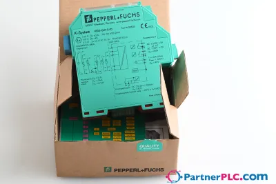 NewPepperl + Fuchs KFD2-GUT-EX1.D New open box
 Available on requestPepperl Fuchs V19-W-BK15M-PUR-U-V19-G
 Available on requestPepperl Fuchs V1SD-G-GN65M-PUR-E1S-V45-G