B&R
X67BC8321

We source discontinued Siemens parts on the surplus market, tested and with warranty.
Request a quote
We source discontinued B&R parts on the surplus market, tested and with warranty.
Request a quote
We source discontinued ABB parts on the surplus market, tested and with warranty.
Request a quote
We source discontinued Schneider Electric parts on the surplus market, tested and with warranty.
Request a quote.svg&w=240)
We source discontinued Allen-Bradley parts on the surplus market, tested and with warranty.
Request a quote
We source discontinued Mitsubishi Electric parts on the surplus market, tested and with warranty.
Request a quote
We source discontinued Beckhoff parts on the surplus market, tested and with warranty.
Request a quote
We source discontinued Lenze parts on the surplus market, tested and with warranty.
Request a quote
We source discontinued Bosch Rexroth parts on the surplus market, tested and with warranty.
Request a quote
We source discontinued Danfoss parts on the surplus market, tested and with warranty.
Request a quote
We source discontinued SEW-Eurodrive parts on the surplus market, tested and with warranty.
Request a quote
We source discontinued KUKA parts on the surplus market, tested and with warranty.
Request a quote
We source discontinued Omron parts on the surplus market, tested and with warranty.
Request a quote
We source discontinued Festo parts on the surplus market, tested and with warranty.
Request a quote
We source discontinued WAGO parts on the surplus market, tested and with warranty.
Request a quote
We source discontinued Pilz parts on the surplus market, tested and with warranty.

We source discontinued SICK parts on the surplus market, tested and with warranty.
Request a quote
We source discontinued Pepperl+Fuchs parts on the surplus market, tested and with warranty.
Request a quote
We source discontinued Balluff parts on the surplus market, tested and with warranty.
Request a quote
We source discontinued ifm parts on the surplus market, tested and with warranty.
Request a quoteWe source discontinued Banner parts on the surplus market, tested and with warranty.
Request a quote
We source discontinued Keyence parts on the surplus market, tested and with warranty.
Request a quote
We source discontinued Honeywell parts on the surplus market, tested and with warranty.
Request a quote
We source discontinued Infineon parts on the surplus market, tested and with warranty.
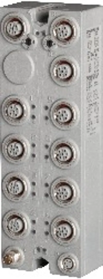
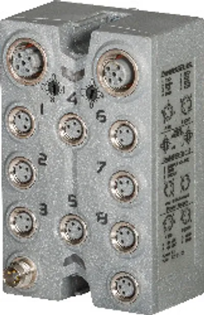
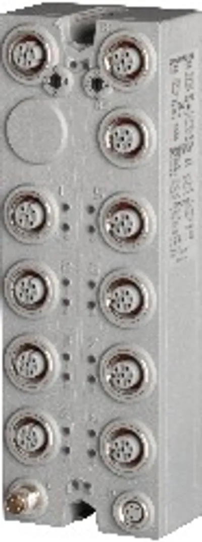
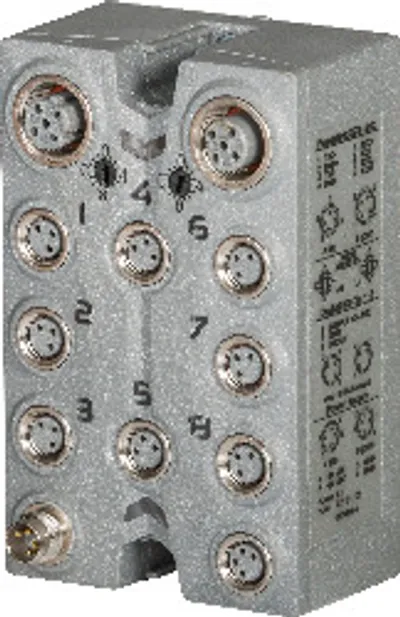
Request a quoteBus controller, POWERLINK (V1/V2) controlled node



POWERLINK V1/V2
Integrated hub for efficient cabling
12 digital channels, configurable as inputs or outputs
1 analog input, 0 to 20 mA, 12 bits
M12 connections
I/O configuration and firmware update via the fieldbus
Integrated connection to the local expansion via X2X Link for up to 250 additional modules
Configurable I/O cycle (starting at 200 µs)
The bus controller makes it possible to connect X2X Link I/O nodes to POWERLINK. It is also possible to operate the X2X Link cycle synchronously 1:1 or synchronous to POWERLINK using a prescaler.
Additional X2X Link I/O nodes (X67 modules or other modules based on X2X Link) can be connected using the integrated X2X Link connection. Mechanically, POWERLINK is connected via an IP67-rated standard D-coded M12 Ethernet connector.
POWERLINK is a standard protocol for Fast Ethernet equipped with hard real-time characteristics. The POWERLINK Standardization Group (EPSG) ensures that the standard remains open and is continually developed:: www.ethernet-powerlink.org .
| Bus controller | POWERLINK (V1/V2) controlled node |
| B&R ID code – Bus controller | 0xB3AC |
| B&R ID code – Internal I/O module | 0xB3CD |
| Diagnostics – Outputs | Yes, using LED status indicator and software |
| Diagnostics – I/O power supply | Yes, using LED status indicator and software |
| Support – Dynamic node allocation (DNA) | Yes |
| Connection type – Fieldbus | M12, D-coded |
| Connection type – X2X Link | M12, B-coded |
| Connection type – Inputs/Outputs | 8x M12, A-coded |
| Connection type – I/O power supply | M8, 4-pin |
| Power consumption – Fieldbus | 2.5 W |
| Power consumption – Internal I/O | 0.6 W |
| Power consumption – X2X Link power supply | 17.25 W at maximum power output for connected I/O modules |
| Certifications – CE | Yes |
| Certifications – UKCA | Yes |
| Certifications – CRA (Cyber Resilience Act) | In preparation |
| Certifications – ATEX | Zone 2, II 3G Ex nA IIA T5 Gc; IP67, Ta = 0 - Max. 60°C; TÜV 05 ATEX 7201X |
| Certifications – UL | cULus E115267; Industrial control equipment |
| Certifications – HazLoc | cCSAus 244665; Process control equipment; for hazardous locations; Class I, Division 2, Groups ABCD, T5 |
| Certifications – KC | Yes |
| Inputs/Outputs | 12 digital channels (configurable as inputs or outputs using the software, inputs with additional functions), 1 analog channel |
| Insulation voltage between channel and bus | 500 V eff |
| Nominal voltage | 24 VDC |
| Sensor/Actuator power supply | 0.5 A summation current |
| Status indicators | I/O function per channel, supply voltage, bus function |
| Power output | 15 W X2X Link power supply for I/O modules |
| Transfer – Physical layer | 100BASE-TX |
| Transfer – Half-duplex | Yes |
| Transfer – Full-duplex | No |
| Transfer – Autonegotiation | Yes |
| Transfer – Auto-MDI/MDIX | Yes |
| Min. cycle time – Fieldbus | 200 μs (note: The minimum cycle time specifies how far the bus cycle can be reduced without communication errors occurring.) |
| Min. cycle time – X2X Link | 200 μs (note: The minimum cycle time specifies how far the bus cycle can be reduced without communication errors occurring.) |
| Fieldbus | POWERLINK (V1/V2) controlled node |
| Type | Type 2Communication / POWERLINK / General information / Hardware - CN" in Automation Help."> (note: For additional information, see section) |
| Variant | 2x M12 interface (hub), 2x female connector on module |
| Line length | Max. 100 m between 2 stations (segment length) |
| Transfer rate | 100 Mbit/s |
| Hub propagation delay | 0.96 to 1 µs |
| Synchronization between bus systems possible | Yes |
| Power consumption – Sensor/Actuator power supply | Max. 12 W (note: The power consumption of the sensors and actuators connected to the module is not permitted to exceed 12 W.) |
| Nominal voltage | 24 VDC |
| Voltage range | 18 to 30 VDC |
| Integrated protective function | Reverse polarity protection |
| Voltage | I/O power supply minus voltage drop for short-circuit protection |
| Voltage drop for short-circuit protection at 0.5 A | Max. 2 VDC |
| Summation current | Max. 0.5 A |
| Short-circuit proof | Yes |
| Input filter – Hardware | ≤10 μs (channels 1 to 4) / ≤70 µs (channels 5 to 12) |
| Input filter – Software | Default 0 ms, configurable between 0 and 25 ms in 0.2 ms intervals |
| Switching threshold – Low | <5 VDC |
| Switching threshold – High | >15 VDC |
| Input characteristics per EN 61131-2 | Type 1 |
| Input voltage | 18 to 30 VDC |
| Input current at 24 VDC | Typ. 4 mA |
| Input circuit | Sink |
| Input resistance | Typ. 6 kΩ |
| Additional functions | 50 kHz event counting, gate measurement |
| Quantity | 1 |
| Signal form | Square wave pulse |
| Evaluation | Each negative edge, cyclic counter |
| Input frequency | Max. 50 kHz |
| Counter 1 | Input 1 |
| Counter frequency | Max. 50 kHz |
| Counter size | 16-bit |
| Counter frequency – Internal | 48 MHz, 3 MHz, 187.5 kHz |
| Quantity | 1 |
| Signal form | Square wave pulse |
| Evaluation | Positive edge - Negative edge |
| Counter size | 16-bit |
| Length of pause between pulses | ≥100 µs |
| Pulse length | ≥20 µs |
| Supported inputs | Input 2 |
| Output format – Current | 0x0000 - 0x7FFF / 1 LSB = 0x0008 = 4.883 μA |
| Output of digital value during overload – Undershoot | 0x0000 |
| Output of digital value during overload – Overshoot | 0x7FFF |
| Max. error – Gain | 0.1% (note: Based on the current measured value.) |
| Max. error – Offset | 0.05% (note: Based on the entire measurement range.) |
| Common-mode rejection – DC | >50 dB |
| Common-mode rejection – 50 Hz | >50 dB |
| Input filter – Cutoff frequency | 1 kHz |
| Input filter – Slope | 40 dB |
| Input | 0 to 20 mA |
| Input type | Differential input |
| Digital converter resolution | 12-bit |
| Conversion time | 200 µs |
| Output format | INT |
| Load | <300 Ω |
| Input protection | Protection against wiring with supply voltage |
| Permissible input signal | Max. ±30 mA |
| Conversion procedure | Successive approximation |
| Max. gain drift | 0.013 %/°C (note: Based on the current measured value.) |
| Max. offset drift | 0.02 %/°C (note: Based on the entire measurement range.) |
| Common-mode range | ±2 V |
| Crosstalk between channels | >70 dB |
| Nonlinearity | <0.1% (note: Based on the entire measurement range.) |
| Insulation voltage between input and bus | 500 V eff |
| Voltage drop at 20 mA | Typ. 4.5 V |
| Switching delay – 0 → 1 | <400 µs |
| Switching delay – 1 → 0 | <400 µs |
| Switching frequency – Resistive load | Max. 100 Hz |
| Switching frequency – Inductive load | See section "Switching inductive loads". |
| Variant | Current-sourcing FET |
| Switching voltage | I/O power supply minus residual voltage |
| Nominal output current | 0.5 A |
| Total nominal current | 8 A |
| Output circuit | Source |
| Output protection | Thermal shutdown in the event of overcurrent or short circuit, integrated protection for switching inductive loads, reverse polarity protection of the output power supply |
| Diagnostic status | Output monitoring with 10 ms delay |
| Leakage current when the output is switched off | 5 µA |
| Switching on after overload shutdown | Approx. 10 ms (depends on the module temperature) |
| R DS(on) | 150 mΩ |
| Residual voltage | <0.3 V at 0.5 A nominal current |
| Peak short-circuit current | <12 A |
| Braking voltage when switching off inductive loads | 50 VDC |
| Electrical isolation | Bus isolated from POWERLINK and channel; Channel not isolated from channel |
| Mounting orientation – Any | Yes |
| Installation elevation above sea level – 0 to 2000 m | No limitation |
| Installation elevation above sea level – >2000 m | Reduction of ambient temperature by 0.5°C per 100 m |
| Degree of protection per EN 60529 | IP67 |
| Temperature – Operation | -25 to 60°C |
| Temperature – Derating | - |
| Temperature – Storage | -40 to 85°C |
| Temperature – Transport | -40 to 85°C |
| Dimensions – Width | 53 mm |
| Dimensions – Height | 155 mm |
| Dimensions – Depth | 42 mm |
| Torque for connections – M8 | Max. 0.4 Nm |
| Torque for connections – M12 | Max. 0.6 Nm |
| Weight | 360 g |
Official documents from B&R, downloaded directly from the manufacturer.
X67BC8513.L12 is sourced on request — request a quote and we'll confirm the exact availability and shipping timeline for this specific unit.
Local pickup from our Groningen, Netherlands warehouse may be possible — contact us before ordering to check availability and arrange a collection time.
Yes — mention it when you request a quote for X67BC8513.L12 and we'll include express shipping options in our reply.
For a critical breakdown, contact us directly at +31 (0)50-7110348 or sales@partnerplc.com — we can look into same-day courier or dedicated taxi/hotshot delivery for X67BC8513.L12, subject to availability and destination.