




.svg&w=240)


















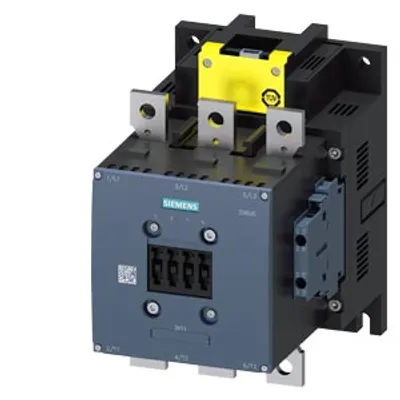
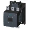
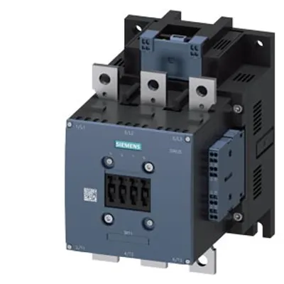
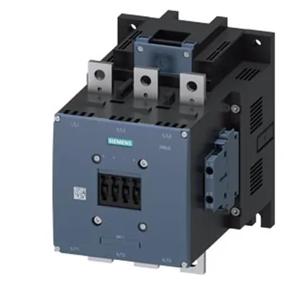
Siemens 3RT1466-6XB46-0LA2
Power contactor AC-1 400 A / 690 V / 40 °C 3-pole
- MPN
- 3RT1466-6XB46-0LA2
Price and lead time confirmed within 1 business day
Request a Quote
- 12-month warranty (new) · 3-month (used/refurbished)
- 30-day returns, no restocking fee on unused parts
- Ships via



What is the Siemens 3RT1466-6XB46-0LA2?
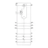
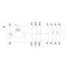
power contactor AC-1 400 A / 690 V / 40 °C 3-pole, Uc: 24 V DC (0.7-1.25) PLC input 24-110 V DC drive: electronic auxiliary contacts 2 NO + 2 NC main circuit: busbar control and auxiliary circuit: screw terminal extended rated condition railroad IEC 60077
Specifications
General
| product brand name | SIRIUS |
| product designation | Power contactor |
| design of the product | With extended operating range |
| product type designation | 3RT14 |
General technical data
| size of contactor | S10 |
| product extension — function module for communication | No |
| product extension — auxiliary switch | Yes |
| power loss [W] for rated value of the current — at AC in hot operating state | 81 W |
| power loss [W] for rated value of the current — at AC in hot operating state per pole | 27 W |
| power loss [W] for rated value of the current — without load current share typical | 3.4 W |
| type of calculation of power loss current-dependent | quadratic |
| insulation voltage — of main circuit with degree of pollution 3 rated value | 1 000 V |
| insulation voltage — of auxiliary circuit with degree of pollution 3 rated value | 500 V |
| surge voltage resistance — of main circuit rated value | 8 kV |
| surge voltage resistance — of auxiliary circuit rated value | 6 kV |
| maximum permissible voltage for protective separation between coil and main contacts according to EN 60947-1 | 690 V |
| shock resistance for railway applications according to EN 61373 | Category 1, Class B |
| shock resistance at rectangular impulse — at DC | 8,5 g / 5 ms, 4,2 g / 10 ms |
| shock resistance with sine pulse — at DC | 13,4 g / 5 ms, 6,5 g / 10 ms |
| mechanical service life (operating cycles) — of contactor typical | 10 000 000 |
| mechanical service life (operating cycles) — of the contactor with added electronically optimized auxiliary switch block typical | 5 000 000 |
| mechanical service life (operating cycles) — of the contactor with added auxiliary switch block typical | 10 000 000 |
| reference code according to IEC 81346-2 | Q |
| Substance Prohibitance (day/month/year) | 09/06/2016 |
| SVHC substance name | Lead CAS-No. 7439-92-1 Lead monoxide (lead oxide) CAS-No. 1317-36-8 2-methyl-1-(4-methylthiophenyl)-2-morpholinopropan-1-one CAS-No. 71868-10-5 Melamine CAS-No. 108-78-1 6,6'-di-tert-butyl-2,2'-methylenedi-p-cresol CAS-No. 119-47-1 |
| Net Weight | 6.199 kg |
Ambient conditions
| installation altitude at height above sea level maximum | 2 000 m |
| ambient temperature — during operation | -40 ... +70 °C |
| ambient temperature — during storage | -55 ... +80 °C |
| relative humidity minimum | 10 % |
| relative humidity at 55 °C according to IEC 60068-2-30 maximum | 95 % |
Main circuit
| number of poles for main current circuit | 3 |
| number of NO contacts for main contacts | 3 |
| number of NC contacts for main contacts | 0 |
| operating voltage — at AC-3 rated value maximum | 690 V |
| operational current — at AC-1 at 400 V at ambient temperature 40 °C rated value | 400 A |
| operational current — at AC-1 — up to 690 V at ambient temperature 40 °C rated value | 400 A |
| operational current — at AC-1 — up to 690 V at ambient temperature 60 °C rated value | 380 A |
| operational current — at AC-2 at 400 V rated value | 138 A |
| operational current — at AC-3 — at 400 V rated value | 138 A |
| operational current — at AC-3 — at 500 V rated value | 138 A |
| operational current — at AC-3 — at 690 V rated value | 138 A |
| minimum cross-section in main circuit — at maximum AC-1 rated value | 240 mm² |
| minimum cross-section in main circuit — at maximum Ith rated value | 240 mm² |
| operational current — at 1 current path at DC-1 — at 24 V rated value | 380 A |
| operational current — at 1 current path at DC-1 — at 110 V rated value | 33 A |
| operational current — at 1 current path at DC-1 — at 220 V rated value | 3.8 A |
| operational current — at 1 current path at DC-1 — at 440 V rated value | 0.9 A |
| operational current — at 1 current path at DC-1 — at 600 V rated value | 0.6 A |
| operational current — with 2 current paths in series at DC-1 — at 24 V rated value | 380 A |
| operational current — with 2 current paths in series at DC-1 — at 110 V rated value | 380 A |
| operational current — with 2 current paths in series at DC-1 — at 220 V rated value | 380 A |
| operational current — with 2 current paths in series at DC-1 — at 440 V rated value | 4 A |
| operational current — with 2 current paths in series at DC-1 — at 600 V rated value | 2 A |
| operational current — with 3 current paths in series at DC-1 — at 24 V rated value | 380 A |
| operational current — with 3 current paths in series at DC-1 — at 110 V rated value | 380 A |
| operational current — with 3 current paths in series at DC-1 — at 220 V rated value | 380 A |
| operational current — with 3 current paths in series at DC-1 — at 440 V rated value | 11 A |
| operational current — with 3 current paths in series at DC-1 — at 600 V rated value | 5.2 A |
| operational current — at 1 current path at DC-3 at DC-5 — at 24 V rated value | 380 A |
| operational current — at 1 current path at DC-3 at DC-5 — at 110 V rated value | 3 A |
| operational current — at 1 current path at DC-3 at DC-5 — at 220 V rated value | 0.6 A |
| operational current — at 1 current path at DC-3 at DC-5 — at 440 V rated value | 0.18 A |
| operational current — at 1 current path at DC-3 at DC-5 — at 600 V rated value | 0.125 A |
| operational current — with 2 current paths in series at DC-3 at DC-5 — at 24 V rated value | 380 A |
| operational current — with 2 current paths in series at DC-3 at DC-5 — at 110 V rated value | 380 A |
| operational current — with 2 current paths in series at DC-3 at DC-5 — at 220 V rated value | 2.5 A |
| operational current — with 2 current paths in series at DC-3 at DC-5 — at 440 V rated value | 0.65 A |
| operational current — with 2 current paths in series at DC-3 at DC-5 — at 600 V rated value | 0.37 A |
| operational current — with 3 current paths in series at DC-3 at DC-5 — at 24 V rated value | 380 A |
| operational current — with 3 current paths in series at DC-3 at DC-5 — at 110 V rated value | 380 A |
| operational current — with 3 current paths in series at DC-3 at DC-5 — at 220 V rated value | 380 A |
| operational current — with 3 current paths in series at DC-3 at DC-5 — at 440 V rated value | 1.4 A |
| operational current — with 3 current paths in series at DC-3 at DC-5 — at 600 V rated value | 0.75 A |
| operating power — at AC-2 at 400 V rated value | 75 kW |
| operating power — at AC-3 — at 230 V rated value | 97 kW |
| operating power — at AC-3 — at 400 V rated value | 75 kW |
| operating power — at AC-3 — at 500 V rated value | 90 kW |
| operating power — at AC-3 — at 690 V rated value | 132 kW |
| short-time withstand current in cold operating state up to 40 °C — limited to 1 s switching at zero current maximum | 5 524 A; Use minimum cross-section acc. to AC-1 rated value |
| short-time withstand current in cold operating state up to 40 °C — limited to 5 s switching at zero current maximum | 4 579 A; Use minimum cross-section acc. to AC-1 rated value |
| short-time withstand current in cold operating state up to 40 °C — limited to 10 s switching at zero current maximum | 3 153 A; Use minimum cross-section acc. to AC-1 rated value |
| short-time withstand current in cold operating state up to 40 °C — limited to 30 s switching at zero current maximum | 1 883 A; Use minimum cross-section acc. to AC-1 rated value |
| short-time withstand current in cold operating state up to 40 °C — limited to 60 s switching at zero current maximum | 1 445 A; Use minimum cross-section acc. to AC-1 rated value |
| no-load switching frequency — at DC | 700 1/h |
| operating frequency — at AC-1 maximum | 600 1/h |
| operating frequency — at DC-1 maximum | 350 1/h |
Ratings for railway applications
| thermal current (Ith) up to 690 V — up to 40 °C according to IEC 60077 rated value | 400 A |
| thermal current (Ith) up to 690 V — up to 70 °C according to IEC 60077 rated value | 330 A |
Control circuit/ Control
| type of voltage | DC |
| type of voltage of the control supply voltage | DC |
| control supply voltage at DC rated value | 24 V |
| operating range factor control supply voltage rated value of magnet coil at DC — initial value | 0.7 |
| operating range factor control supply voltage rated value of magnet coil at DC — full-scale value | 1.25 |
| consumed current at PLC-control input according to IEC 60947-1 maximum | 2 mA |
| voltage at PLC-control input | 24 ... 110 V |
| design of the surge suppressor | with varistor |
| closing power of magnet coil at DC | 580 W |
| holding power of magnet coil at DC | 3.4 W |
| closing delay — at DC | 45 ... 80 ms |
| opening delay — at DC | 80 ... 100 ms |
| arcing time | 10 ... 15 ms |
| control version of the switch operating mechanism | PLC-IN or Standard A1 - A2 (adjustable) |
Auxiliary circuit
| number of NC contacts for auxiliary contacts | 2 |
| number of NC contacts for auxiliary contacts — instantaneous contact | 2 |
| number of NO contacts for auxiliary contacts | 2 |
| number of NO contacts for auxiliary contacts — instantaneous contact | 2 |
| operational current at AC-12 maximum | 10 A |
| operational current at AC-15 — at 230 V rated value | 6 A |
| operational current at AC-15 — at 400 V rated value | 3 A |
| operational current at AC-15 — at 500 V rated value | 2 A |
| operational current at DC-12 — at 24 V rated value | 10 A |
| operational current at DC-12 — at 48 V rated value | 6 A |
| operational current at DC-12 — at 60 V rated value | 6 A |
| operational current at DC-12 — at 110 V rated value | 3 A |
| operational current at DC-12 — at 125 V rated value | 2 A |
| operational current at DC-12 — at 220 V rated value | 1 A |
| operational current at DC-12 — at 600 V rated value | 0.15 A |
| operational current at DC-13 — at 24 V rated value | 6 A |
| operational current at DC-13 — at 48 V rated value | 2 A |
| operational current at DC-13 — at 60 V rated value | 2 A |
| operational current at DC-13 — at 110 V rated value | 1 A |
| operational current at DC-13 — at 125 V rated value | 0.9 A |
| operational current at DC-13 — at 220 V rated value | 0.3 A |
| operational current at DC-13 — at 600 V rated value | 0.1 A |
UL/CSA ratings
| full-load current (FLA) for 3-phase AC motor — at 480 V rated value | 156 A |
| full-load current (FLA) for 3-phase AC motor — at 600 V rated value | 144 A |
| yielded mechanical performance [hp] — for 3-phase AC motor — at 220/230 V rated value | 60 hp |
| yielded mechanical performance [hp] — for 3-phase AC motor — at 460/480 V rated value | 125 hp |
| yielded mechanical performance [hp] — for 3-phase AC motor — at 575/600 V rated value | 150 hp |
| contact rating of auxiliary contacts according to UL | A600 / Q600 |
Short-circuit protection
| design of the miniature circuit breaker for short-circuit protection of the auxiliary circuit up to 230 V | C characteristic: 10 A; 0.4 kA |
| design of the fuse link — for short-circuit protection of the main circuit — with type of coordination 1 required | gG: 500 A (690 V, 100 kA) |
| design of the fuse link — for short-circuit protection of the main circuit — with type of coordination 2 required | gR: 500 A (690 V, 100 kA) |
| design of the fuse link — for short-circuit protection of the auxiliary switch required | gG: 10 A (500 V, 1 kA) |
Installation/ mounting/ dimensions
| mounting position | with vertical mounting surface +/-90° rotatable, with vertical mounting surface +/- 22.5° tiltable to the front and back |
| fastening method side-by-side mounting | Yes |
| fastening method | screw fixing |
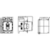
| height | 210 mm |
| width | 145 mm |
| depth | 202 mm |
| required spacing — with side-by-side mounting — forwards | 20 mm |
| required spacing — with side-by-side mounting — upwards | 10 mm |
| required spacing — with side-by-side mounting — downwards | 10 mm |
| required spacing — with side-by-side mounting — at the side | 10 mm |
| required spacing — for grounded parts — forwards | 20 mm |
| required spacing — for grounded parts — upwards | 10 mm |
| required spacing — for grounded parts — at the side | 10 mm |
| required spacing — for grounded parts — downwards | 10 mm |
| required spacing — for live parts — forwards | 20 mm |
| required spacing — for live parts — upwards | 10 mm |
| required spacing — for live parts — downwards | 10 mm |
| required spacing — for live parts — at the side | 10 mm |
Connections/ Terminals
| type of electrical connection — for main current circuit | screw-type terminals |
| type of electrical connection — for auxiliary and control circuit | screw-type terminals |
| width of connection bar | 25 mm |
| thickness of connection bar | 6 mm |
| diameter of holes | 11 mm |
| number of holes | 1 |
| type of connectable conductor cross-sections — for main contacts — solid or stranded | 2x (70 ... 240 mm²) |
| type of connectable conductor cross-sections — for AWG cables for main contacts | 2/0 ... 500 kcmil |
| type of connectable conductor cross-sections — for auxiliary contacts — solid | 2x (0.5 ... 1.5 mm²), 2x (0.75 ... 2.5 mm²), max. 2x (0.75 ... 4 mm²) |
| type of connectable conductor cross-sections — for auxiliary contacts — solid or stranded | 2x (0,5 ... 1,5 mm²), 2x (0,75 ... 2,5 mm²), max. 2x (0,75 ... 4 mm²) |
| type of connectable conductor cross-sections — for auxiliary contacts — finely stranded with core end processing | 2x (0.5 ... 1.5 mm²), 2x (0.75 ... 2.5 mm²) |
| type of connectable conductor cross-sections — for AWG cables for auxiliary contacts | 2x (20 ... 16), 2x (18 ... 14), 1x 12 |
| AWG number as coded connectable conductor cross section for auxiliary contacts | 18 ... 14 |
Safety related data
| product function — mirror contact according to IEC 60947-4-1 | Yes |
| product function — positively driven operation according to IEC 60947-5-1 | No |
| protection class IP on the front according to IEC 60529 | IP00; IP20 with box terminal/cover |
| touch protection on the front according to IEC 60529 | finger-safe, for vertical contact from the front with box terminal/cover |
Communication/ Protocol
| product function bus communication | No |
Downloads & documentation
Official documents from Siemens, downloaded directly from the manufacturer.
Data sheets & manuals
3RT1466-6XB46-0LA2: frequently asked questions
When can 3RT1466-6XB46-0LA2 be shipped?
3RT1466-6XB46-0LA2 is sourced on request — request a quote and we'll confirm the exact availability and shipping timeline for this specific unit.
Can I pick up 3RT1466-6XB46-0LA2 in person?
Local pickup from our Groningen, Netherlands warehouse may be possible — contact us before ordering to check availability and arrange a collection time.
Is express delivery available?
Yes — mention it when you request a quote for 3RT1466-6XB46-0LA2 and we'll include express shipping options in our reply.
My factory is down and I need this urgently — can you help?
For a critical breakdown, contact us directly at +31 (0)50-7110348 or sales@partnerplc.com — we can look into same-day courier or dedicated taxi/hotshot delivery for 3RT1466-6XB46-0LA2, subject to availability and destination.
More Siemens parts


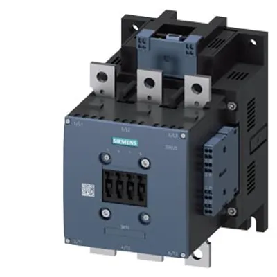

Siemens 3RT1466-6XB46-0LA2Price and lead time confirmed within 1 business day
Request a Quote