























 New
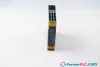

SiemensNew
Siemens 3SK1121-1AB40
Safety Technology
- MPN
- 3SK1121-1AB40
- Category
- Safety Technology
€259.70excl. VAT & shipping
In stock — 1 available·Ships within 1 business day
Need a larger quantity or a formal quote?
Request a Quote
- 12-month warranty
- 30-day returns, no restocking fee on unused parts
- Ships via



- 100% positive eBay feedback
What is the Siemens 3SK1121-1AB40?
Safety Technology
Specifications
Product Function
| Technical Product Detail Page | https://i.siemens.com/1P3SK1121-1AB40 |
| product function parameterizable | sensor floating / sensor non-floating, monitored start-up / automatic start, 1-channel / 2-channel sensor connection, cross-circuit detection, startup testing, antivalent sensors, 2-hand switches |
| product function — automatic start | Yes |
| product function — light barrier monitoring | Yes |
| product function — protective door monitoring | Yes |
| product function — magnetically operated switch monitoring NC-NO | Yes |
| product function — magnetically operated switch monitoring NC-NC | Yes |
| product function — laser scanner monitoring | Yes |
| product function — light array monitoring | Yes |
| product function — EMERGENCY OFF function | Yes |
| product function — monitored start-up | Yes |
| product function — pressure-sensitive mat monitoring | No |
| product feature cross-circuit-proof | Yes |
| suitability for interaction press control | Yes |
| suitability for operation device connector 3ZY12 | Yes |
| suitability for use — monitoring of floating sensors | Yes |
| suitability for use — monitoring of non-floating sensors | Yes |
| suitability for use — position switch monitoring | Yes |
| suitability for use — EMERGENCY-OFF circuit monitoring | Yes |
| suitability for use — opto-electronic protection device monitoring | Yes |
| suitability for use — magnetically operated switch monitoring | Yes |
| suitability for use — safety-related circuits | Yes |
General technical data
| certificate of suitability UL approval | Yes |
| product feature protective coating on printed-circuit board | No |
| power loss [W] maximum | 2 W |
| insulation voltage rated value | 300 V |
| degree of pollution | 3 |
| overvoltage category | 3 |
| surge voltage resistance rated value | 4 000 V |
| protection class IP of the enclosure | IP20 |
| shock resistance | 10 g / 11 ms |
| vibration resistance according to IEC 60068-2-6 | 5 ... 500 Hz: 0.75 mm |
| operating frequency maximum | 360 1/h |
| reference code according to IEC 81346-2 | F |
| Substance Prohibitance (day/month/year) | 11/05/2012 |
| SVHC substance name | Lead CAS-No. 7439-92-1 Lead monoxide (lead oxide) CAS-No. 1317-36-8 2-methyl-1-(4-methylthiophenyl)-2-morpholinopropan-1-one CAS-No. 71868-10-5 Melamine CAS-No. 108-78-1 6,6'-di-tert-butyl-2,2'-methylenedi-p-cresol CAS-No. 119-47-1 4,4'-isopropylidenediphenol (Bisphenol A, BPA) CAS-No. 80-05-7 |
| Net Weight | 240.96 g |
Ambient conditions
| installation altitude at height above sea level maximum | 4 000 m |
| note | Derating, see Product Notification 109792701 |
| ambient temperature — during operation | -25 ... +60 °C |
| ambient temperature — during storage | -40 ... +80 °C |
| relative humidity during operation | 10 ... 95 % |
| air pressure according to SN 31205 | 900 ... 1 060 hPa |
Electromagnetic compatibility
| installation environment regarding EMC | This product is suitable for Class A environments only. In household environments, this device can cause unwanted radio interference. The user is required to implement appropriate measures in this case. |
| EMC emitted interference | IEC 60947-5-1, Class A |
Safety related data
| product function suitable for safety function | Yes |
| safe state | Safety outputs switched off |
| test wear-related service life necessary | Yes |
| function test interval maximum | 1 a |
| diagnostics test interval by internal test function maximum | 600 s |
| stop category according to IEC 60204-1 | 0 |
| SIL Claim Limit (subsystem) according to EN 62061 | 3 |
| Safety Integrity Level (SIL) — according to IEC 62061 | SIL 3 |
| Safety Integrity Level (SIL) — at single-channel evaluation according to IEC 62061 | 1 |
| Safety Integrity Level (SIL) — at 2-channel evaluation according to IEC 62061 | 3 |
| PFHD with high demand rate according to IEC 62061 | 0,0000000025 |
| category according to EN ISO 13849-1 | 4 |
| performance level (PL) — according to ISO 13849-1 | PL e |
| performance level (PL) — at single-channel evaluation according to ISO 13849-1 | c |
| performance level (PL) — at 2-channel evaluation according to ISO 13849-1 | e |
| category — according to ISO 13849-1 | 4 |
| category — at 2-channel evaluation according to ISO 13849-1 | 4 |
| overdimensioning according to ISO 13849-2 necessary | No |
| Safety Integrity Level (SIL) — according to IEC 61508 | 3 |
| Safety Integrity Level (SIL) — at single-channel evaluation according to IEC 61508 | 1 |
| Safety Integrity Level (SIL) — at 2-channel evaluation according to IEC 61508 | 3 |
| safety device type according to IEC 61508-2 | Type B |
| PFHD with high demand rate according to IEC 61508 | 0,0000000025 |
| PFDavg with low demand rate according to IEC 61508 | 0.000007 |
| Safe failure fraction (SFF) | 99 % |
| hardware fault tolerance — according to IEC 61508 | 1 |
| hardware fault tolerance — at single-channel evaluation according to IEC 61508 | 0 |
| hardware fault tolerance — at 2-channel evaluation according to IEC 61508 | 1 |
| T1 value — of service life according to IEC 61508 | 20 a |
| T1 value — for proof test interval or service life according to IEC 61508 | 20 a |
| touch protection against electrical shock | finger-safe |
Short-circuit protection
| design of the fuse link — for short-circuit protection of the NO contacts of the relay outputs required | gL/gG: 6A or circuit breaker type A: 3A or circuit breaker type B: 2A or circuit breaker type C: 1A |
| design of the fuse link — for short circuit protection of the NC contacts of the relay outputs required | Diazed or Neozed fuses, operating class gL/gG: 6 A or MCB type A: 2 A or MCB type B: 2 A or MCB type C: 1 A |
Inputs
| design of input — cascading input/functional switching | Yes |
| design of input — feedback input | Yes |
| design of input — start input | Yes |
| pulse duration of the sensor input minimum | 75 ms |
| number of sensor inputs 1-channel or 2-channel | 1 |
Outputs
| — for signaling function instantaneous contact | 1 |
| — safety-related instantaneous contact | 3 |
| — safety-related delayed switching | 0 |
| mechanical service life (operating cycles) typical | 10 000 000 |
| thermal current of the switching element with contacts maximum | 5 A |
| switching capacity current of the NO contacts of the relay outputs at DC-13 — at 24 V | 5 A |
| switching capacity current of the NO contacts of the relay outputs at DC-13 — at 115 V | 0.2 A |
| switching capacity current of the NO contacts of the relay outputs at DC-13 — at 230 V | 0.1 A |
| switching capacity current of the NO contacts of the relay outputs at AC-15 — at 115 V | 5 A |
| switching capacity current of the NO contacts of the relay outputs at AC-15 — at 230 V | 5 A |
| switching capacity current of the NC contacts of the relay outputs at DC-13 — at 24 V | 1 A |
| switching capacity current of the NC contacts of the relay outputs at DC-13 — at 115 V | 0.2 A |
| switching capacity current of the NC contacts of the relay outputs at DC-13 — at 230 V | 0.1 A |
| switching capacity current of the NC contacts of the relay outputs at AC-15 — at 24 V | 2 A |
| switching capacity current of the NC contacts of the relay outputs at AC-15 — at 115 V | 1.5 A |
| switching capacity current of the NC contacts of the relay outputs at AC-15 — at 230 V | 1.5 A |
| total current maximum | 12 A |
| operational current at 17 V minimum | 5 mA |
Times
| make time with automatic start — at DC maximum | 110 ms |
| make time with automatic start after power failure — typical | 6 500 ms |
| make time with automatic start after power failure — maximum | 6 500 ms |
| make time with monitored start — maximum | 110 ms |
| backslide delay time after opening of the safety circuits typical | 40 ms |
| backslide delay time in the event of power failure — typical | 30 ms |
| backslide delay time in the event of power failure — maximum | 50 ms |
| recovery time after opening of the safety circuits typical | 30 ms |
| recovery time after power failure typical | 6.5 s |
| pulse duration — of the ON pushbutton input minimum | 0.15 s |
Control circuit/ Control
| type of voltage of the control supply voltage | DC |
| control supply voltage at DC rated value | 24 V |
| operating range factor control supply voltage rated value of magnet coil at DC — initial value | 0.8 |
| operating range factor control supply voltage rated value of magnet coil at DC — full-scale value | 1.2 |
Installation/ mounting/ dimensions
| mounting position | any |
| fastening method | screw and snap-on mounting |
| height | 100 mm |
| width | 22.5 mm |
| depth | 121.6 mm |
| required spacing — for grounded parts at the side | 5 mm |
Connections/ Terminals
| type of electrical connection | screw terminal |
| wire length — with Cu 1.5 mm² and 150 nF/km per sensor circuit maximum | 4 000 m |
| type of connectable conductor cross-sections — solid | 1x (0.5 ... 2.5 mm²), 2x (1.0 ... 1.5 mm²) |
| type of connectable conductor cross-sections — finely stranded with core end processing | 1x (0.5 ... 2.5 mm²), 2x (0.5 ... 1.0 mm²) |
| type of connectable conductor cross-sections — for AWG cables solid | 1x (20 ... 14), 2x (18 ... 16) |
| type of connectable conductor cross-sections — for AWG cables stranded | 1x (20 ... 16), 2x (20 ... 16) |
| type of electrical connection plug-in socket | No |
Downloads & documentation
Official documents from Siemens, downloaded directly from the manufacturer.
Data sheets & manuals
3SK1121-1AB40: frequently asked questions
When can 3SK1121-1AB40 be shipped?
3SK1121-1AB40 is in stock and typically ships within 1 business day via UPS, DHL or FedEx, worldwide.
Can I pick up 3SK1121-1AB40 in person?
Local pickup from our Groningen, Netherlands warehouse may be possible — contact us before ordering to check availability and arrange a collection time.
Is express delivery available?
Yes — alongside standard UPS, DHL and FedEx shipping, express (next-day) delivery is available at checkout for in-stock items like 3SK1121-1AB40.
My factory is down and I need this urgently — can you help?
For a critical breakdown, contact us directly at +31 (0)50-7110348 or sales@partnerplc.com — we can look into same-day courier or dedicated taxi/hotshot delivery for 3SK1121-1AB40, subject to availability and destination.
More Siemens parts
New New
 New
 New
Siemens 3SK1121-1AB40€259.70
Buy Now