




.svg&w=240)


















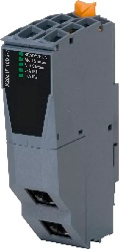
B&R X20CM0985
I/O module, X20 energy measurement and synchronization…
- MPN
- X20CM0985
- Category
- Other functions
Price and lead time confirmed within 1 business day
Request a Quote
- 12-month warranty (new) · 3-month (used/refurbished)
- 30-day returns, no restocking fee on unused parts
- Ships via



What is the B&R X20CM0985?
Energy measurement for 120 to 480 VAC
Simultaneous measurement of 2 AC mains networks plus 2 additional voltages
For multifunctional measurement tasks
Intelligent mains synchronization unit
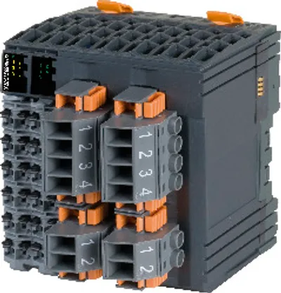
The module has a compact size and combines a power measurement module that has special features with a synchronization unit that is able to meet all demands.
The measurement unit's 3 current inputs are suitable for both X: 1 A and X: 5 A current transformers. Overcurrent resistance and the high resolution of the measurement unit round off its features. For the voltage inputs, the value range can be configured between 480 VAC and 120 VAC .
The area of use includes 4-wire AC networks with a phase voltage up to 480 VAC and 3-wire systems, whereas L2 can be grounded (V-connection). The module can also handle Aron measuring circuits.
The resulting measured values include the pure phase current; line-to-line voltage or phase voltage; the effective, reactive and apparent power parts; the mains frequency; the power factor and much more. In addition, peak values and energy meters are stored on the module in nonvolatile memory. Depending on the configuration, it is also possible to use a digital output as a pulse encoder for an external energy meter.
The synchronization unit doesn't just take the phasing and phase voltage into consideration; integrated intelligence also monitors the rate of change and other parameters, allowing them to influence when the synchronization output is switched. It is also possible to monitor a generator using a large number of additional conditions. A total of 4 voltage inputs provide substantial overall flexibility.
Monitoring functions expand the features of the module. Dependent overcurrent monitoring is included, which utilizes the thermal capacity of the motor/generator to allow short overloads while still providing full protection. The dependent, delayed imbalanced load monitoring used to protect three-phase generator and three-phase networks from imbalanced load can be adapted to the characteristics of different generator types using parameters while taking their special thermal time constants into account.
Specifications
Short description
| I/O module | X20 energy measurement and synchronization module |
General information
| Diagnostics – Module run/error | Yes, using LED status indicator and software |
| Diagnostics – Analog inputs | Yes, using LED status indicator (measurement range of analog inputs) |
| Diagnostics – Digital outputs | Yes, using LED status indicator and software |
| Power consumption – Bus | 1.4 W |
| Power consumption – Internal I/O | 4 W |
| Certifications – CE | Yes |
| Certifications – UKCA | Yes |
| Certifications – CRA (Cyber Resilience Act) | In preparation |
| Certifications – ATEX | Zone 2, II 3G Ex nA nC IIA T5 Gc; IP20, Ta (see X20 user's manual); FTZÚ 09 ATEX 0083X |
| Certifications – UL | cULus E115267; Industrial control equipment |
| Certifications – HazLoc | cCSAus 244665; Process control equipment; for hazardous locations; Class I, Division 2, Groups ABCD, T5 |
| Certifications – KC | Yes |
| B&R ID code | 0x2433 |
| Status indicators | Channel status, operating state, module status |
| Overvoltage category | ll (note: EN 61131-2) |
| Additional power dissipation caused by actuators (resistive) [W] | - |
Digital outputs
| Switching delay – 0 → 1 | <300 μs |
| Switching delay – 1 → 0 | <300 μs |
| Switching frequency – Resistive load | Max. 100 Hz |
| Quantity | 5 |
| Variant | Current-sourcing FET |
| Nominal voltage | 24 VDC |
| Switching voltage | 24 VDC -15% / +20% |
| Nominal output current | 0.1 A |
| Total nominal current | 0.5 A |
| Connection type | 1-wire connections |
| Output circuit | Source |
| Output protection | Thermal shutdown in the event of overcurrent or short circuit |
| Diagnostic status | Output monitoring with 10 ms delay |
| Leakage current when the output is switched off | 5 μA |
| Residual voltage | <0.3 V at 0.1 A nominal current |
| Peak short-circuit current | <2 A |
| Switch-on in the event of overload shutdown or short-circuit shutdown | Approx. 10 ms, depends on the module temperature |
| Insulation voltage between channel and bus | 500 V eff |
Relay outputs
| Switching capacity – Min. | 10 mA / 5 VDC |
| Switching capacity – Max. | 30 W / 240 VAC |
| Switching delay – 0 → 1 | ≤10 ms |
| Switching delay – 1 → 0 | ≤10 ms |
| Service lifeElectrical service life"."> – Mechanical | Min. 10 x 10 6 ops. (note: See section) |
| Service lifeElectrical service life"."> – Electrical | Min. 60 x 10 3 ops. (NC) at 1 A; Min. 30 x 10 3 ops. (NO) at 1 A (note: See section) |
| Protective circuit – Internal | None |
| Protective circuit – External | None |
| Protective circuit – DC | Inverse diode, RC combination or VDR |
| Protective circuit – AC | RC combination or VDR |
| Insulation voltage – Channel - Channel | 1000 VAC / 1 min |
| Insulation voltage – Channel - Bus | 4000 VAC / 1 min |
| Quantity | 1 |
| Variant | Relay / Changeover contact |
| Nominal voltage | 30 VDC / 240 VAC |
| Rated frequency | DC / 45 to 63 Hz |
| Nominal output current | 1 A at 30 VDC / 1 A at 240 VAC |
| Actuator power supply | External |
| Switching voltage | Max. 60 VDC / 250 VAC |
| Contact resistance | Max. 100 mΩ |
Analog input voltage
| Conversion time – 50 Hz | 20 ms |
| Conversion time – 60 Hz | 16.67 ms |
| Output format – ±120 VAC | 1 LSB = 0x0001 = 5.707 mV (note: INT, range of values: 0x8001 to 0x7FFF) |
| Output format – ±480 VAC | 1 LSB = 0x0001 = 22.787 mV (note: INT, range of values: 0x8001 to 0x7FFF) |
| Output of digital value during overload – Overshoot | 0x7FFF |
| Output of digital value during overload – Undershoot | 0x8001 |
| Input filter – Cutoff frequency | 10 kHz |
| Input filter – Slope | 60 dB |
| Max. error at 25°C – Gain | 0.09% (note: Based on the current measured value) |
| Max. error at 25°C – Offset | 0.03% (note: Based on the measurement range 240 VAC / 960 VAC) |
| Channels | 8 |
| Input | 120 VAC / 480 VAC |
| Input type | Single-ended |
| Digital converter resolution | ±15-bit |
| Permissible input signal | Max. 132 VAC / 528 VAC |
| Conversion method | SAR |
| Maximum gain drift | 0.02% per °C (note: Based on the current measured value) |
| Maximum offset drift | 0.003% per °C (note: Based on the measurement range 240 VAC / 960 VAC) |
| Crosstalk between channels | -70 dB |
| Nonlinearity | ≤0.5% at 45 to 65 Hz (note: Based on the measurement range 240 VAC / 960 VAC) |
| Protection against electric shock | Protective impedance per EN 61131-2 |
| Test voltage between channel and bus (type test) | 3700 V eff |
| Output format | INT |
| Input impedance in signal range | Approx. 3 MΩ |
| Input protection | Overvoltage protection |
Analog input current
| Conversion time – 50 Hz | 20 ms |
| Conversion time – 60 Hz | 16.67 ms |
| Output format – ±1 A | 1 LSB = 0x0001 = 189.903 μA (note: INT, range of values: 0x8001 to 0x7FFF) |
| Output format – ±5 A | 1 LSB = 0x0001 = 949.513 μA (note: INT, range of values: 0x8001 to 0x7FFF) |
| Output of digital value during overload – Overshoot | 0x7FFF |
| Output of digital value during overload – Undershoot | 0x8001 |
| Input filter – Cutoff frequency | 10 kHz |
| Input filter – Slope | 60 dB |
| Max. error at 25°C – Gain | 0.2% (note: Based on the current measured value) |
| Max. error at 25°C – Offset | 0.05% (note: Based on the measurement range 2 A / 10 A) |
| Input impedance – Measurement range 1 A | Max. 30 mΩ (note: Including current transformer, circuit path and X20TB12 terminal block (5 mΩ)) |
| Input impedance – Measurement range 5 A | Max. 10 mΩ (note: Including current transformer, circuit path and X20TB12 terminal block (5 mΩ)) |
| Channels | 3 |
| Input | 1 A / 5 A AC |
| Input type | Isolated current transformer according to the compensation principle with a magnetic sensor, for connecting an external transformer |
| Digital converter resolution | ±15-bit |
| Permissible input signal | Max. 1.5 A / 7.7 A |
| Conversion method | SAR |
| Maximum gain drift | 0.07% per °C (note: Based on the current measured value) |
| Maximum offset drift | 0.003% per °C (note: Based on the measurement range 2 A / 10 A) |
| Crosstalk between channels | -70 dB |
| Nonlinearity | ≤0.5% at 45 to 65 Hz (note: Based on the measurement range 2 A / 10 A) |
| Insulation voltage between channel and bus | 500 V eff |
| Output format | INT |
| Thermal overcurrent | 15 x I Nom for 0.2 s (note: Based on the measurement range 1 A / 5 A) |
| Monitored overcurrent | 4 x I Nom (note: Based on the measurement range 1 A / 5 A) |
Electrical properties
| Electrical isolation | Bus isolated from I/O power supply and digital inputs and outputs ; Digital inputs and outputs isolated from each other |
Operating conditions
| Mounting orientation – Horizontal | Yes |
| Mounting orientation – Vertical | Yes |
| Installation elevation above sea level – 0 to 2000 m | No limitation |
| Installation elevation above sea level – >2000 m | Reduction of ambient temperature by 0.5°C per 100 m |
| Degree of protection per EN 60529 | IP20 |
Ambient conditions
| Temperature – Horizontal mounting orientation | 0 to 60°C |
| Temperature – Vertical mounting orientation | 0 to 50°C |
| Temperature – Derating | See section "Derating". |
| Temperature – Storage | -40 to 85°C |
| Temperature – Transport | -40 to 85°C |
| Relative humidity – Operation | 5 to 95%, non-condensing |
| Relative humidity – Storage | 5 to 95%, non-condensing |
| Relative humidity – Transport | 5 to 95%, non-condensing |
Mechanical properties
| Note | Order 2x terminal block X20TB12 separately. ; Order 2x screw clamp terminal block TB3102 and 2x screw clamp terminal block TB3104 separately. |
| Pitch | 87.5 +0.2 mm |
Accessories
Required accessories (order separately)
| X20TB12 | Terminal blocks — Tool-free wiring with push-in technology; Simple wire release using lever; Ability to label each terminal; Plain text labeling also possibl… |
| 0TB3104-7012 | Terminal blocks — The single row 4-pin terminal block 0TB3104 is used for making connections on an X20 energy measurement module. |
| 0TB3104-7011 | Terminal blocks — The single row 4-pin terminal block 0TB3104 is used for making connections on an X20 energy measurement module. |
| 0TB3102-7012 | Terminal blocks — The single row 2-pin terminal block 0TB3102 is used for making connections on an X20 energy measurement module. |
| 0TB3102-7011 | Terminal blocks — Accessory terminal block, 2-pin, A-coded, screw clamp terminal block 6 mm² |
Downloads & documentation
Official documents from B&R, downloaded directly from the manufacturer.
Data sheets & manuals
CAD & dimension drawings
X20CM0985: frequently asked questions
When can X20CM0985 be shipped?
X20CM0985 is sourced on request — request a quote and we'll confirm the exact availability and shipping timeline for this specific unit.
Can I pick up X20CM0985 in person?
Local pickup from our Groningen, Netherlands warehouse may be possible — contact us before ordering to check availability and arrange a collection time.
Is express delivery available?
Yes — mention it when you request a quote for X20CM0985 and we'll include express shipping options in our reply.
My factory is down and I need this urgently — can you help?
For a critical breakdown, contact us directly at +31 (0)50-7110348 or sales@partnerplc.com — we can look into same-day courier or dedicated taxi/hotshot delivery for X20CM0985, subject to availability and destination.
More B&R parts
B&R X20CM0985Price and lead time confirmed within 1 business day
Request a Quote