
























B&R X20cAI2438
I/O module, 2 analog inputs 4 to 20 mA or 0 to 25 mA
- MPN
- X20cAI2438
- Category
- Analog inputs
Price and lead time confirmed within 1 business day
Request a Quote
- 12-month warranty (new) · 3-month (used/refurbished)
- 30-day returns, no restocking fee on unused parts
- Ships via



What is the B&R X20cAI2438?
2 analog current measurement inputs
Integrated HART protocol
Supports HART variables
Electrically isolated analog channels
Electrically isolated sensor supplies
16-bit digital converter resolution
NetTime timestamp: Moment of measurement, HART image
Specifications
Short description
| I/O module | 2 analog inputs 4 to 20 mA or 0 to 25 mA |
General information
| Diagnostics – Module run/error | Yes, using LED status indicator and software |
| Diagnostics – Inputs | Yes, using LED status indicator and software |
| Diagnostics – Sensor power supply | Yes, using LED status indicator and software |
| Diagnostics – HART link | Yes, using LED status indicator and software |
| Diagnostics – HART error | Yes, using LED status indicator and software |
| Power consumption – Bus | 0.05 W |
| Power consumption – Internal I/O | 1.15 W (note: To reduce power dissipation, B&R recommends leaving unused inputs open.) |
| Certifications – CE | Yes |
| Certifications – UKCA | Yes |
| Certifications – CRA (Cyber Resilience Act) | In preparation |
| Certifications – ATEX | Zone 2, II 3G Ex nA nC IIA T5 Gc; IP20, Ta (see X20 user's manual); FTZÚ 09 ATEX 0083X |
| Certifications – UL | cULus E115267; Industrial control equipment |
| Certifications – HazLoc | cCSAus 244665; Process control equipment; for hazardous locations; Class I, Division 2, Groups ABCD, T5 |
| Certifications – DNV | Temperature: B (0 to 55°C); Humidity: B (up to 100%); Vibration: B (4 g); EMC: B (bridge and open deck) |
| Certifications – LR | ENV1 |
| Certifications – KR | Yes |
| Certifications – ABS | Yes |
| Certifications – BV | EC33B ; Temperature: 5 - 55°C; Vibration: 4 g; EMC: Bridge and open deck |
| B&R ID code | 0xE1EE |
| Status indicators | I/O function per channel, operating state, module status, sensor power supply per channel, HART |
| Additional power dissipation caused by actuators (resistive) [W] | - |
Analog inputs
| Data output rate – With HART | 4.7 to 10 samples per second, configurable using software |
| Data output rate – Analog | 4.7 to 100 samples per second, configurable using software |
| Output format – 4 to 20 mA | INT 0x0000 - 0x7FFF / 1 LSB = 0x0001 = 488.281 nA |
| Output format – 0 to 25 mA | INT 0x0000 - 0x7FFF / 1 LSB = 0x0001 = 762.939 nA |
| Output format – 0 to 25000 µA | INT 0x0000 - 0x61A8 / 1 LSB = 0x0001 = 1000 nA |
| Max. error – 0 to 25 mA | <0.046% (note: Based on the current measured value.) |
| Max. error – 4 to 20 mA | <0.046% (note: Based on the current measured value.) |
| Max. error – 0 to 25 mA | <0.004% (note: Based on the 25 mA measurement range.) |
| Max. error – 4 to 20 mA | <0.013% (note: Based on the 25 mA measurement range.) |
| Common-mode rejection – DC | 80 dB |
| Common-mode rejection – 50 Hz | Depends on the sampling rate: e.g. >130 dB for 50 samples per second |
| Input filter – Hardware | First-order low-pass filter / cutoff frequency 100 Hz |
| Input filter – Software | Sinc 4 filter |
| Max. gain drift – 0 to 25 mA | 0.003 %/°C (note: Based on the current measured value.) |
| Max. gain drift – 4 to 20 mA | 0.003 %/°C (note: Based on the current measured value.) |
| Max. offset drift – 0 to 25 mA | 0.0002 %/°C (note: Based on the 25 mA measurement range.) |
| Max. offset drift – 4 to 20 mA | 0.0007 %/°C (note: Based on the 25 mA measurement range.) |
| Test voltage – Channel - Channel | 1000 VAC |
| Test voltage – Channel - Bus | 1000 VAC |
| Test voltage – Channel - Ground | 1000 VAC |
| Input | 4 to 20 mA or 0 to 25 mA configurable using software |
| Input type | Differential input |
| Digital converter resolution | 16-bit |
| Output format | INT |
| Load | I_IN ≥ 0.1 mA: R < 8000 Ω ; I_IN ≥ 1 mA: R < 1100 Ω ; I_IN ≥ 4 mA: R < 510 Ω |
| Input protection | Up to 30 VDC, reverse polarity protection (max. 0.1 A) |
| Open-circuit detection | Yes, using software |
| Permissible input signal | 0 to 25 mA |
| Output of digital value during overload | Configurable |
| Conversion procedure | Sigma-delta |
| Common-mode range | 0 to 7 V |
| Nonlinearity | <0.003% (note: Based on the 25 mA measurement range.) |
Sensor power supply
| Max. voltage ripple – Up to 100 kHz | ≤2.2 mV |
| Max. voltage ripple – Up to 1 MHz | ≤22 mV |
| Max. voltage ripple – Higher | ≤100 mV |
| Short-circuit current – Typical | <50 mA |
| Short-circuit current – Maximum | 60 mA |
| Power consumption | 0.75 W per channel |
| Nominal voltage | 25 V ±2% |
| Nominal output current | Max. 30 mA |
| Short-circuit proof | Yes, continuous |
| Behavior on short circuit | Current limiting |
HART
| Multi-drop operation – Possible | Yes |
| Multi-drop operation – Stations | 5 nodes (when using HART slaves with a nominal current of 4 mA); Up to 15 (taking into account the maximum permissible input signal of 25 mA) |
| Transmission amplitude – Minimum | 400 mV pp |
| Transmission amplitude – Typical | 500 mV pp |
| Transmission amplitude – Maximum | 600 mV pp |
| Receiving amplitude – Minimum | 120 mV pp |
| Receiving amplitude – Maximum | 800 mV pp |
| Transfer rate | 1200 bit/s |
| Operating frequencies | 1200 Hz / 2200 Hz |
| Burst operation possible | Yes |
Electrical properties
| Electrical isolation | Channel isolated from channel and bus; Sensor power supply isolated from sensor power supply; Sensor power supply not isolated from channel |
Operating conditions
| Mounting orientation – Horizontal | Yes |
| Mounting orientation – Vertical | Yes |
| Installation elevation above sea level – 0 to 2000 m | No limitation |
| Installation elevation above sea level – >2000 m | Reduction of ambient temperature by 0.5°C per 100 m |
| Degree of protection per EN 60529 | IP20 |
Ambient conditions
| Temperature – Horizontal mounting orientation | -25 to 60°C |
| Temperature – Vertical mounting orientation | -25 to 50°C |
| Temperature – Derating | - |
| Temperature – Starting temperature | Yes, -40°C |
| Temperature – Storage | -40 to 85°C |
| Temperature – Transport | -40 to 85°C |
| Relative humidity – Operation | Up to 100%, condensing |
| Relative humidity – Storage | 5 to 95%, non-condensing |
| Relative humidity – Transport | 5 to 95%, non-condensing |
Mechanical properties
| Note | Order 1x terminal block X20TB12 separately. ; Order 1x bus module X20cBM11 separately. |
| Pitch | 12.5 +0.2 mm |
Accessories
Required accessories (order separately)
| X20cBM11 | Bus modules — Bus module for 24 VDC I/O modules; The internal I/O power supply is connected through. |
| X20TB12 | Terminal blocks — Tool-free wiring with push-in technology; Simple wire release using lever; Ability to label each terminal; Plain text labeling also possibl… |
Downloads & documentation
Official documents from B&R, downloaded directly from the manufacturer.
Data sheets & manuals
CAD & dimension drawings
Certificates (13)
- 2226379 CSA Certificate of Compliance X20 X67
- ABS Certificate of Product Design Assessment - X20 IO Series
- E115267 UL Certificate of Compliance X20
- EU Data Act - X20 IO - Connected Product Information Notice
- EU Declaration ATEX X20
- EU Declaration of conformity PLC X20
- FTZU 09 ATEX 0083X
- KR Type Approval Certificate MIL39390-AC003 (X20 System)
- Lloyds Register (X20 only)
- RINA Type Approval Certificate - X20 / Power Panel T30
- TAA00000BJ DNV Type Approval Certificate X20
- UK Declaration ACOPOSmicro
- UK Declaration PLC X20
X20cAI2438: frequently asked questions
When can X20cAI2438 be shipped?
X20cAI2438 is sourced on request — request a quote and we'll confirm the exact availability and shipping timeline for this specific unit.
Can I pick up X20cAI2438 in person?
Local pickup from our Groningen, Netherlands warehouse may be possible — contact us before ordering to check availability and arrange a collection time.
Is express delivery available?
Yes — mention it when you request a quote for X20cAI2438 and we'll include express shipping options in our reply.
My factory is down and I need this urgently — can you help?
For a critical breakdown, contact us directly at +31 (0)50-7110348 or sales@partnerplc.com — we can look into same-day courier or dedicated taxi/hotshot delivery for X20cAI2438, subject to availability and destination.
More B&R parts

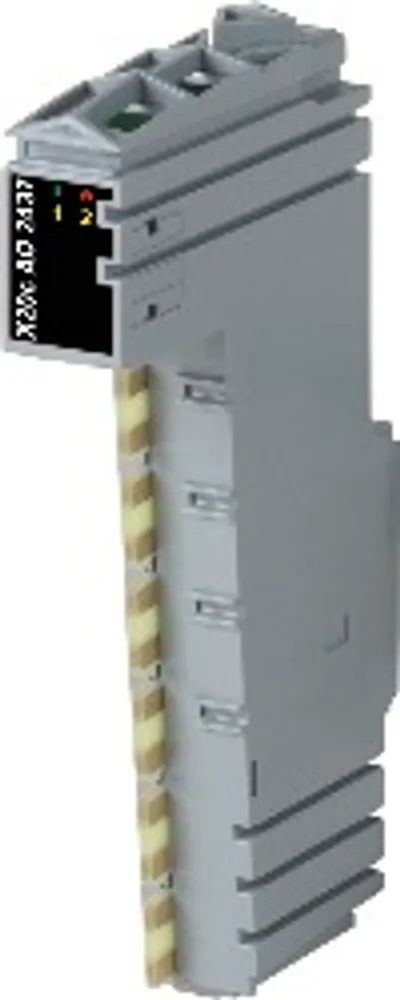
B&R X20cAI2438Price and lead time confirmed within 1 business day
Request a Quote