




.svg&w=240)


















B&R X20RT8381 – I/O module, 4 digital input channels
Request a Quote



Quick facts
| Availability | Confirmed on request |
| Category | reACTION Technology modules |
| Lifecycle | Active |
| Warranty | 12-month (new) · 3-month (used/refurbished) |
| Datasheet | Manufacturer datasheet ↗ |
Shipping & availability
When can X20RT8381 be shipped?
X20RT8381 is sourced on request — request a quote and we'll confirm the exact availability and shipping timeline for this specific unit.
Can I pick up X20RT8381 in person?
Local pickup from our Groningen, Netherlands warehouse may be possible — contact us before ordering to check availability and arrange a collection time.
Is express delivery available?
Yes — mention it when you request a quote for X20RT8381 and we'll include express shipping options in our reply.
My factory is down and I need this urgently — can you help?
For a critical breakdown, contact us directly at +31 (0)50-7110348 or sales@partnerplc.com — we can look into same-day courier or dedicated taxi/hotshot delivery for X20RT8381, subject to availability and destination.
• reACTION Technology module
• 4 high-speed digital inputs
• 4 high-speed digital channels, configurable as inputs or outputs
• 2 high-speed analog inputs ±10 V
• 1 high-speed analog output ±10 V
• 1 ABR incremental encoder input 24 V
• Pulse width modulation
• Support of data type "REAL" for arithmetic operations
• Supports blackout mode
This reACTION Technology module is equipped with 4 high-speed digital inputs and 4 high-speed digital mixed channels. All connections are designed for 1-wire connections . All inputs are designed for sink connections; the outputs are designed for push-pull connections.
A voltage signal of ±10 V can be read or output using 2 analog inputs and 1 analog output, respectively.
Ultrafast reACTION Technology makes it possible to control the integrated I/O channels with response times down to 1 μs . All of the commands that can be used for reACTION programs are provided as function blocks in special libraries ( e.g. AsIORTI). Programming in compliance with IEC 61131-3 requirements takes place in the Function Block Diagram editor in Automation Studio.
The module supports blackout mode. In blackout mode, programmable module functionality persists even if the network fails.
Accessories
Required accessories (order separately)
| X20BM31 | Bus modules — Bus module for double-width I/O modules; The internal I/O supply is interconnected The bus module serves as a basis for all double-width X2… |
| X20TB12 | Terminal blocks — Tool-free wiring with push-in technology; Simple wire release using lever; Ability to label each terminal; Plain text labeling also possibl… |
Specifications
Short description
| I/O module | 4 digital input channels, 4 digital channels configurable as inputs or outputs, 2 analog inputs ±10 V, 1 analog output ±10 V, reACTION Technology |
General information
| Diagnostics – Module run/error | Yes, using LED status indicator and software |
| Diagnostics – Outputs | Yes, using LED status indicator and software (output error status) |
| Diagnostics – Inputs | Yes, using LED status indicator and software |
| Diagnostics – Channel type | Yes, using software |
| Support – reACTION-capable I/O channels | Yes |
| Blackout mode – Scope | Module |
| Blackout mode – Function | Programmable |
| Blackout mode – Standalone mode | No |
| Power consumption – Bus | 0.01 W |
| Power consumption – Internal I/O | 1.7 W |
| Application memory – Type | 64 Mbit flash memory |
| Application memory – Data retention | 20 years at 55°C |
| Application memory – Guaranteed erase/write cycles | 100,000 |
| Certifications – CE | Yes |
| Certifications – UKCA | Yes |
| Certifications – CRA (Cyber Resilience Act) | In preparation |
| Certifications – UL | cULus E115267; Industrial control equipment |
| Certifications – DNV | Temperature: B (0 to 55°C); Humidity: B (up to 100%); Vibration: B (4 g); EMC: B (bridge and open deck) |
| Certifications – CCS | Yes |
| Certifications – LR | ENV1 |
| Certifications – KR | Yes |
| Certifications – ABS | Yes |
| Certifications – BV | EC33B ; Temperature: 5 - 55°C; Vibration: 4 g; EMC: Bridge and open deck |
| B&R ID code | 0xF24E |
| Status indicators | I/O function per channel, operating state, module status |
| Additional power dissipation caused by actuators (resistive) [W] | +1.1 |
| Type of signal linesX20 shielding brackets"."> | Shielded lines must be used for all signal lines, line length: Max. 20 m (note: See section) |
Digital inputs
| Input filter – Hardware | <3 µs |
| Input filter – Software | Default 200 ns, configurable between 200 ns and 5 ms in 10 ns intervals |
| Switching threshold – Low | <5 VDC |
| Switching threshold – High | >15 VDC |
| Quantity | 4 standard inputs and 4 mixed channels, configuration as input or output using software |
| Nominal voltage | 24 VDC |
| Input voltage | 24 VDC -15% / +20% |
| Input current at 24 VDC | Typ. 1.3 mA |
| Input circuit | Sink |
| Connection type | 1-wire connections |
| Input resistance | 18.16 kΩ |
| Insulation voltage between channel and bus | 500 V eff |
ABR incremental encoder
| Quantity | 1 |
| Encoder inputs | 24 V, asymmetrical |
| Counter size | 32-bit |
| Input frequency | Max. 333 kHz |
| Evaluation | 4x |
Analog inputs
| Output format – Data type | INT |
| Output format – Voltage | INT 0x8001 - 0x7FFF / 1 LSB = 0x0008 = 2.441 mV |
| Output of digital value during overload – Undershoot | 0x8001 |
| Output of digital value during overload – Overshoot | 0x7FFF |
| Max. error – Gain | 0.08% (note: Based on the current measured value.) |
| Max. error – Offset | 0.018% (note: Based on the 20 V measurement range.) |
| Common-mode rejection – DC | 86 dB |
| Common-mode rejection – 50 Hz | 84 dB |
| Quantity | 2 (note: To reduce power dissipation, B&R recommends bridging unused inputs on the terminal.) |
| Input | ±10 V |
| Input type | Differential input |
| Digital converter resolution | ±12-bit |
| Input impedance in signal range | 20 MΩ |
| Input protection | Protection against wiring with supply voltage |
| Permissible input signal | Max. ±30 V |
| Conversion procedure | SAR |
| Input filter | Third-order low-pass filter / Cutoff frequency 130 kHz |
| Max. gain drift | 0.003 %/°C (note: Based on the current measured value.) |
| Max. offset drift | 0.001%/°C (note: Based on the 20 V measurement range.) |
| Common-mode range | ±12 V |
| Nonlinearity | 0.015% (note: Based on the 20 V measurement range.) |
| Insulation voltage between channel and bus | 500 V eff |
| Sampling frequency | 500 kHz |
Digital outputs
| Switching delay – 0 → 1 | <1 µs |
| Switching delay – 1 → 0 | <1 µs |
| Switching frequency – Resistive load | Max. 500 kHz |
| QuantityDerating and hardware configuration"."> | 4 mixed channels, configuration as input or output using software (note: See section) |
| Variant | Push-Pull |
| Nominal voltage | 24 VDC |
| Switching voltage | 24 VDC -15% / +20% |
| Nominal output current | 100 mA |
| Total nominal current | 400 mA |
| Connection type | 1-wire connections |
| Output circuit | Sink or source |
| Output protection | Thermal shutdown in the event of overcurrent or short circuit (see value "Short-circuit peak current") |
| Diagnostic status | Output monitoring with delay <700 ns |
| Leakage current when the output is switched off | Approx. 25 µA |
| R DS(on) | 140 mΩ |
| Residual voltage | <0.4 V at nominal current 100 mA |
| Max. continuous current | 100 mA |
| Peak short-circuit current | <10 A |
| Switch-on in the event of overload shutdown or short-circuit shutdown | Approx. 3 ms |
| Insulation voltage between channel and bus | 500 V eff |
Analog outputs
| Max. error – Gain | 0.15% (note: Based on the current output value.) |
| Max. error – Offset | 0.05% (note: Based on the entire output range.) |
| Output format – Data type | INT |
| Output format – Voltage | INT 0x8000 - 0x7FFF / 1 LSB = 0x0008 = 2.441 mV |
| Quantity | 1 |
| Output | ±10 V |
| Digital converter resolution | ±12-bit |
| Conversion time | 2 μs |
| Settling time on output change over entire range | 5 μs |
| Switch on/off behavior | Internal enable relay for startup |
| Output protection | Short-circuit proof |
| Load per channel | Max. ±10 mA, load ≥1 kΩ |
| Short-circuit proof | Current limiting ±65 mA |
| Output filter | First-order low-pass filter / cutoff frequency 22 kHz |
| Max. gain drift | 0.022 %/°C (note: Based on the current output value.) |
| Max. offset drift | 0.032%/°C (note: Based on the entire output range.) |
| Error caused by load change | Max. 0.14%, from 10 MΩ → 1 kΩ, resistive |
| Nonlinearity | 0.005% (note: Based on the output range.) |
| Insulation voltage between channel and bus | 500 V eff |
Electrical properties
| Electrical isolation | Channel isolated from bus; Channel not isolated from channel |
Operating conditions
| Mounting orientation – Horizontal | Yes |
| Mounting orientation – Vertical | Yes |
| Installation elevation above sea level – 0 to 2000 m | No limitation |
| Installation elevation above sea level – >2000 m | Reduction of ambient temperature by 0.5°C per 100 m |
| Degree of protection per EN 60529 | IP20 |
Ambient conditions
| Temperature – Horizontal mounting orientation | -25 to 60°C |
| Temperature – Vertical mounting orientation | -25 to 50°C |
| Temperature – Derating | See section "Derating and hardware configuration". |
| Temperature – Storage | -40 to 85°C |
| Temperature – Transport | -40 to 85°C |
| Relative humidity – Operation | 5 to 95%, non-condensing |
| Relative humidity – Storage | 5 to 95%, non-condensing |
| Relative humidity – Transport | 5 to 95%, non-condensing |
Mechanical properties
| Note | Order 2x terminal block X20TB12 separately. ; Order 1x bus module X20BM31 separately. |
| Pitch | 25 +0.2 mm |
Downloads & documentation
Official documents from B&R, downloaded directly from the manufacturer.
Data sheets & manuals
| Data sheet X20RT8381 | PDF · 2 MB · 1.23 (06/03/2026) - EN |
| X20 System User´s Manual | PDF · 50 MB · 4.40 (03/10/2026) - EN |
| reACTION Technology user´s manual | PDF · 13 MB · 1.22 (03/16/2026) - EN |
CAD & dimension drawings
| 3D File DXFSTEP X20 Double IO Slice | ZIP · 117 KB · 1.00 (08/29/2019) |
Certificates (10)
| 64331_A1 BV Certificate of Compliance X20 | PDF · 1 MB · 2026_05 (05/05/2026) |
| CCS Type Approval Certificate - X20 | PDF · 285 KB · 1.00 (06/28/2024) |
| E115267 UL Certificate of Compliance X20 | PDF · 3 MB · 2026_08_27 (08/27/2026) |
| EU Data Act - X20 IO - Connected Product Information Notice | PDF · 92 KB · 1.00 (09/30/2025) |
| EU Declaration ATEX X20 | PDF · 218 KB · 2023-07 (09/05/2023) |
| EU Declaration of conformity PLC X20 | PDF · 169 KB · 2021/10 (11/08/2021) |
| KR Type Approval Certificate MIL39390-AC003 (X20 System) | PDF · 320 KB · 2.0 (05/05/2025) |
| Lloyds Register (X20 only) | PDF · 884 KB · 1.30 (07/07/2025) |
| TAA00000BJ DNV Type Approval Certificate X20 | PDF · 186 KB · 13.0 (05/04/2026) |
| UK Declaration PLC X20 | PDF · 151 KB · 2024-01 (01/18/2024) |
More B&R parts
 Available on requestB&R X20PS9602 – Power supply module, 24 VDC power supply module for…
 Available on requestB&R X20RT8001 – I/O module, 4 digital input channels
 Available on requestB&R X20RT8201 – I/O module, 4 digital input channels
 Available on requestB&R X20RT8202 – I/O module, 4 digital input channels
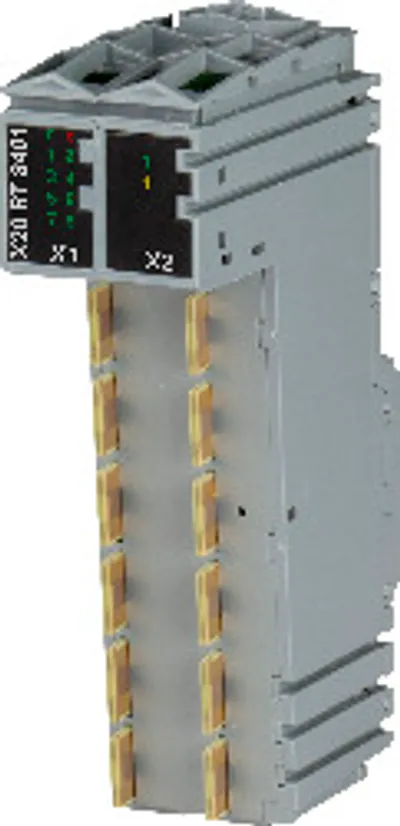 Available on requestB&R X20RT8401 – I/O module, 4 digital input channels
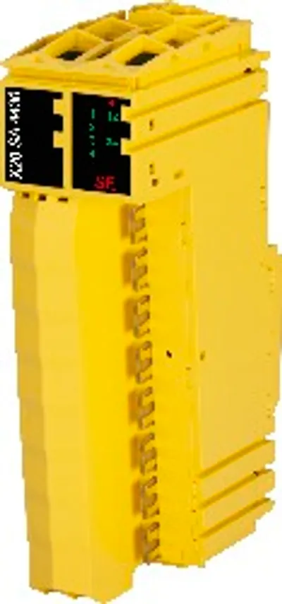 Available on requestB&R X20SA4430 – I/O module, 2x 2 safe type A analog inputs, 0.5 to 25 mA
 Available on requestX20SBD4M1 ACOPOS X2 universal drives, • 2 motor connections • Universal motor interface • Universal encoder interface
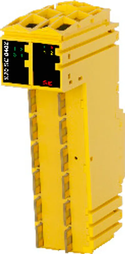 Available on requestB&R X20SC0402 – I/O module, 4 safe type A digital inputs, 4 pulse outputs