
B&R X67AI2744 – I/O module, 2 full-bridge strain gauge inputs
Request a Quote



Quick facts
| Availability | Confirmed on request |
| Category | Analog input modules |
| Lifecycle | Active |
| Warranty | 12-month (new) · 3-month (used/refurbished) |
| Weight | 190 kg |
| Datasheet | Manufacturer datasheet ↗ |
Shipping & availability
When can X67AI2744 be shipped?
X67AI2744 is sourced on request — request a quote and we'll confirm the exact availability and shipping timeline for this specific unit.
Can I pick up X67AI2744 in person?
Local pickup from our Groningen, Netherlands warehouse may be possible — contact us before ordering to check availability and arrange a collection time.
Is express delivery available?
Yes — mention it when you request a quote for X67AI2744 and we'll include express shipping options in our reply.
My factory is down and I need this urgently — can you help?
For a critical breakdown, contact us directly at +31 (0)50-7110348 or sales@partnerplc.com — we can look into same-day courier or dedicated taxi/hotshot delivery for X67AI2744, subject to availability and destination.
• 2 full-bridge strain gauge inputs
• Data output rate configurable from 2.5 Hz to 7.5 kHz
The module is equipped with 2 inputs for evaluating full-bridge strain gauges and works with both 4-wire and 6-wire strain gauge load cells. The concept applied by the module requires calibration in the measurement system. This calibration compensates or eliminates the absolute inaccuracies in the measurement circuit ( e.g. component tolerances, effective bridge voltage or zero offset). The measuring accuracy related to an absolute (calibrated) value only changes due to the negative influence of a change in the operating temperature.
Specifications
Short description
| I/O module | 2 full-bridge strain gauge inputs |
General information
| Diagnostics – Module run/error | Yes, using LED status indicator and software |
| Diagnostics – Open circuit | Yes, using LED status indicator and software |
| Diagnostics – Input | Yes, using LED status indicator and software |
| Connection type – X2X Link | M12, B-coded |
| Connection type – Inputs | 4x M12, A-coded |
| Connection type – I/O power supply | M8, 4-pin |
| Power consumption – Bus | 0.75 W |
| Power consumption – Internal I/O | 2.4 W |
| Certifications – CE | Yes |
| Certifications – UKCA | Yes |
| Certifications – CRA (Cyber Resilience Act) | In preparation |
| Certifications – ATEX | Zone 2, II 3G Ex nA IIA T5 Gc; IP67, Ta = 0 - Max. 60°C; TÜV 05 ATEX 7201X |
| Certifications – UL | cULus E115267; Industrial control equipment |
| Certifications – HazLoc | cCSAus 244665; Process control equipment; for hazardous locations; Class I, Division 2, Groups ABCD, T5 |
| Certifications – KC | Yes |
| B&R ID code | 0x8820 |
| Status indicators | Channel status, operating state, module status |
I/O power supply
| Nominal voltage | 24 VDC |
| Voltage range | 18 to 30 VDC |
| Integrated protective function | Reverse polarity protection |
Full-bridge strain gauge
| Input filter – Cutoff frequency | 5 kHz |
| Input filter – Order | 3 |
| Input filter – Slope | 60 dB |
| Output of digital value – Broken bridge supply line | Value approaching 0 |
| Output of digital value – Broken sensor line | Value approaching ±end value (status bit "Line monitoring" is set in register "Module status") |
| Output of digital value – Valid range of values | 0xFF800001 to 0x007FFFFF (-8,388,607 to 8,388,607) |
| Strain gauge supply – Voltage | 5.5 VDC / Max. 65 mA |
| Strain gauge supply – Short-circuit and overload-proof | Yes |
| Strain gauge supply – Voltage drop for short-circuit protection | Max. 0.2 VDC at 65 mA and 25°C |
| Quantization " data-placement="top" data-html="true" data-container="body" data-content="Quantization depends on the strain gauge factor."> – 2 mV/V | 336 nV |
| Quantization " data-placement="top" data-html="true" data-container="body" data-content="Quantization depends on the strain gauge factor."> – 4 mV/V | 671 nV |
| Quantization " data-placement="top" data-html="true" data-container="body" data-content="Quantization depends on the strain gauge factor."> – 8 mV/V | 1.343 µV |
| Quantization " data-placement="top" data-html="true" data-container="body" data-content="Quantization depends on the strain gauge factor."> – 16 mV/V | 2.686 µV |
| Quantization " data-placement="top" data-html="true" data-container="body" data-content="Quantization depends on the strain gauge factor."> – 32 mV/V | 5.371 µV |
| Quantization " data-placement="top" data-html="true" data-container="body" data-content="Quantization depends on the strain gauge factor."> – 64 mV/V | 10.74 µV |
| Quantization " data-placement="top" data-html="true" data-container="body" data-content="Quantization depends on the strain gauge factor."> – 128 mV/V | 21.48 µV |
| Quantization " data-placement="top" data-html="true" data-container="body" data-content="Quantization depends on the strain gauge factor."> – 256 mV/V | 42.97 µV |
| Quantization " data-placement="top" data-html="true" data-container="body" data-content="Quantization depends on the strain gauge factor."> – 2 mV/V | 1.31 nV |
| Quantization " data-placement="top" data-html="true" data-container="body" data-content="Quantization depends on the strain gauge factor."> – 4 mV/V | 2.62 nV |
| Quantization " data-placement="top" data-html="true" data-container="body" data-content="Quantization depends on the strain gauge factor."> – 8 mV/V | 5.25 nV |
| Quantization " data-placement="top" data-html="true" data-container="body" data-content="Quantization depends on the strain gauge factor."> – 16 mV/V | 10.49 nV |
| Quantization " data-placement="top" data-html="true" data-container="body" data-content="Quantization depends on the strain gauge factor."> – 32 mV/V | 20.98 nV |
| Quantization " data-placement="top" data-html="true" data-container="body" data-content="Quantization depends on the strain gauge factor."> – 64 mV/V | 41.96 nV |
| Quantization " data-placement="top" data-html="true" data-container="body" data-content="Quantization depends on the strain gauge factor."> – 128 mV/V | 83.92 nV |
| Quantization " data-placement="top" data-html="true" data-container="body" data-content="Quantization depends on the strain gauge factor."> – 256 mV/V | 167.85 nV |
| Strain gauge factor | 2 to 256 mV/V, configurable using software |
| Connection | 4- or 6-wire connections " data-placement="top" data-html="true" data-container="body" data-content="With 6-wire connections, line compensation does not function (see section "Connection examples")."> |
| Input type | Differential, used to evaluate a full-bridge strain gauge |
| Digital converter resolution | 24-bit |
| Conversion time | Depends on the configured data output rate |
| Data output rate | 2.5 to 7,500 samples per second, configurable using software (f DATA ) |
| ADC filter characteristics | Sigma-delta, see section "Filter characteristics of the sigma-delta A/D converter" |
| Operating range / Measurement sensor | 85 to 5,000 Ω |
| Influence of cable length " data-placement="top" data-html="true" data-container="body" data-content="Sensor cable with twisted and shielded conductors, cable length as short as possible, cable routing separate from load circuits, without intermediate terminal to the sensor."> | See section "Calculation example", sensor cable length: Max. 30 m |
| Input protection | RC protection |
| Common-mode range | 0 to 3 VDC ; Permissible input voltage range (with regard to the electric potential strain gauge GND) on inputs "Input +" and "Input -" |
| Insulation voltage between input and bus | 500 V eff |
| Conversion procedure | Sigma-delta |
| Max. gain drift | 12 ppm/°C " data-placement="top" data-html="true" data-container="body" data-content="Based on the current measured value."> |
| Max. offset drift | 2 ppm/°C " data-placement="top" data-html="true" data-container="body" data-content="Based on the entire measurement range."> |
| Nonlinearity | <10 ppm " data-placement="top" data-html="true" data-container="body" data-content="Based on the entire measurement range."> |
Electrical properties
| Electrical isolation | Bus isolated from analog input and strain gauge supply voltage ; Channel not isolated from I/O power supply |
Operating conditions
| Mounting orientation – Horizontal | Yes |
| Mounting orientation – Vertical | Yes |
| Installation elevation above sea level – 0 to 2000 m | No limitation |
| Installation elevation above sea level – >2000 m | Reduction of ambient temperature by 0.5°C per 100 m |
| Degree of protection per EN 60529 | IP67 |
Ambient conditions
| Temperature – Operation | -25 to 60°C |
| Temperature – Derating | - |
| Temperature – Storage | -40 to 85°C |
| Temperature – Transport | -40 to 85°C |
Mechanical properties
| Dimensions – Width | 53 mm |
| Dimensions – Height | 85 mm |
| Dimensions – Depth | 42 mm |
| Torque for connections – M8 | Max. 0.4 Nm |
| Torque for connections – M12 | Max. 0.6 Nm |
| Weight | 190 g |
Downloads & documentation
Official documents from B&R, downloaded directly from the manufacturer.
Data sheets & manuals
| Data sheet X67AI2744 | PDF · 3 MB · 4.10 (09/05/2025) - EN |
| X67 System User´s Manual | PDF · 21 MB · 4.40 (08/27/2026) - EN |
CAD & dimension drawings
| 3D File DXF/STEP X67 | ZIP · 2 MB · 1.20 (03/17/2025) |
Certificates (6)
| E115267 UL CoC X67 | PDF · 345 KB · 2026_01 (01/29/2026) |
| EU Declaration ATEX X67 | PDF · 191 KB · 2021-04 (07/02/2021) |
| EU Declaration PLC X67 | PDF · 674 KB · 2024-02 (02/02/2024) |
| TÜV 05 ATEX 7201 X | PDF · 5 MB · 1.10 (03/24/2021) |
| UK Declaration PLC X67 | PDF · 469 KB · 2024-02 (02/02/2024) |
| X20, X67 KC certificates | PDF · 7 MB · 2.00 (08/17/2026) |
More B&R parts
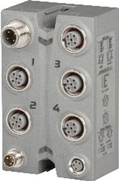 Available on requestB&R X67AI1223 – I/O module, 4 analog inputs ±10 V
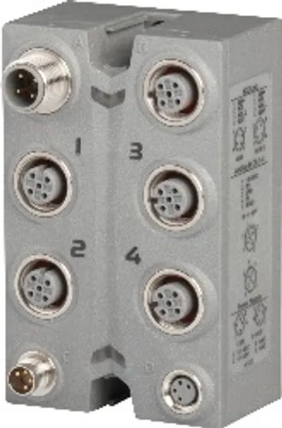 Available on requestB&R X67AI1233 – I/O module, 4 analog inputs ±10 V
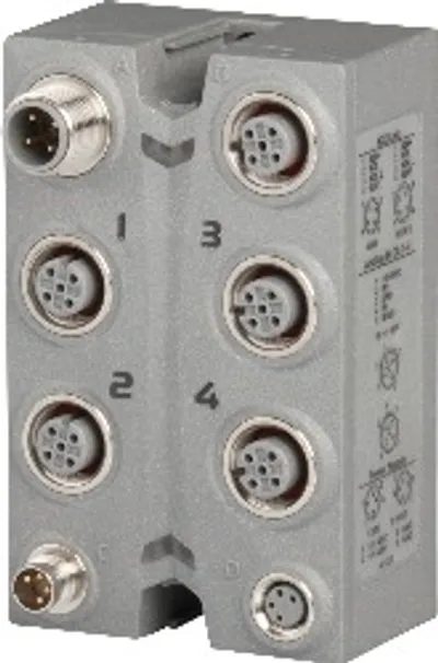 Available on requestB&R X67AI1323 – I/O module, 4 analog inputs 0 to 20 mA or 4 to 20 mA
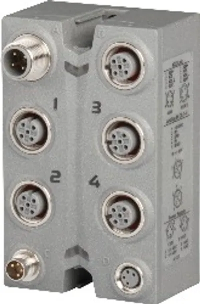 Available on requestB&R X67AI1333 – I/O module, 4 analog inputs 0 to 20 mA or 4 to 20 mA
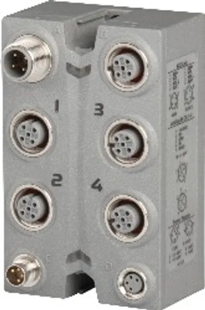 Available on requestB&R X67AI4850 – I/O module, 4 inputs for potentiometer displacement gauge
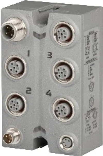 Available on requestB&R X67AM1223 – I/O module, 2 analog inputs, 2 analog outputs, each ±10 V
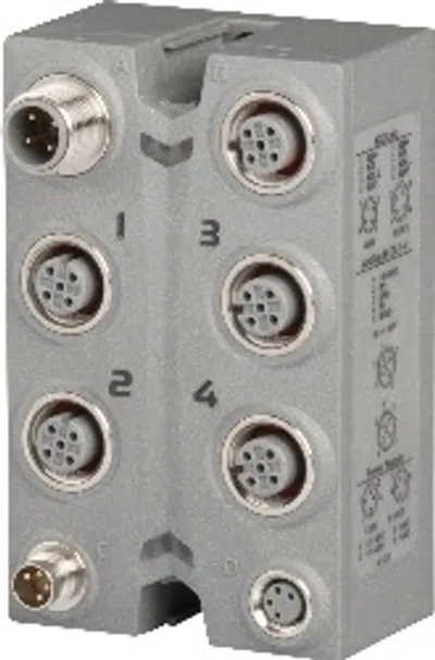 Available on requestB&R X67AM1323 – I/O module, 2 analog inputs, 2 analog outputs
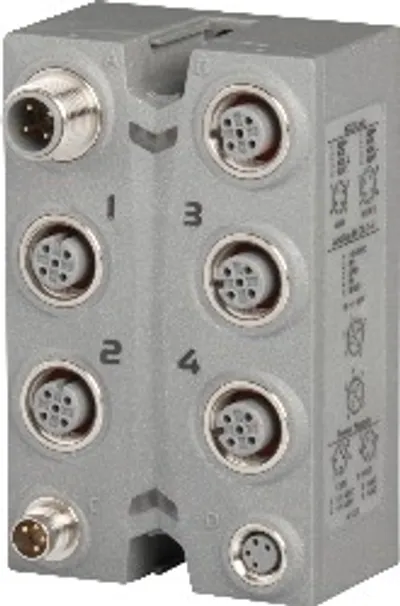 Available on requestB&R X67AO1223 – I/O module, 4 analog outputs ±10 V