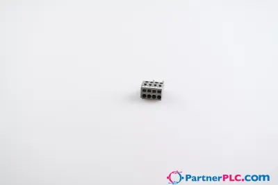
Fail-safe 8 channel digital output; 24 VDC; 0.5 A; PROFIsafe
Request a Quote



Quick facts
| Availability | Confirmed on request |
| Category | I/O Systems |
| Lifecycle | active |
| Warranty | 12-month (new) · 3-month (used/refurbished) |
Shipping & availability
When can 750-1665/000-004 be shipped?
750-1665/000-004 is sourced on request — request a quote and we'll confirm the exact availability and shipping timeline for this specific unit.
Can I pick up 750-1665/000-004 in person?
Local pickup from our Groningen, Netherlands warehouse may be possible — contact us before ordering to check availability and arrange a collection time.
Is express delivery available?
Yes — mention it when you request a quote for 750-1665/000-004 and we'll include express shipping options in our reply.
My factory is down and I need this urgently — can you help?
For a critical breakdown, contact us directly at +31 (0)50-7110348 or sales@partnerplc.com — we can look into same-day courier or dedicated taxi/hotshot delivery for 750-1665/000-004, subject to availability and destination.
This module (Item No. 750-1665/000-004) has 8 power outputs (O1+ ... O8+).<br/>The power outputs switch resistive, capacitive and inductive loads according to DC 13 with a nominal current of up to 0.5 A without external additional circuit.<br/>The power outputs can be operated unipolar (common potential on one side of the load).<br/>Short circuit and 24 V power supply are monitored.<br/>The PROFIsafe address is set on the coding switch located on the side, via WAGO-I/O-CHECK or via the Safe Controller Engineering Tool.<br/>The module supports PROFIsafe protocols V2.4 and V2.6 (PROFIBUS and PROFINET).<br/>Field and system levels are electrically isolated from each other.<br/>The individual safe modules can be arranged as required when configuring the fieldbus node.<br/>If required (e.g., cable length of the 24 V power supply greater than 3 m), a WAGO filter module or a suitable external filter must be used for the 24 V power supply to protect against surge and burst (per EN 61000-6-7, EN 61326-3-1 and marine applications).<br/>For more information, see the manual (German and English).<br/>The module (Item No. 75x-1665/000-004) was evaluated by UL in accordance with UL/CSA 61010-1, UL/CSA 61010-2-201 and UL 121201, CSA-C22.2 No. 213.<br/>The functional safety assessment according to the above standards was carried out by TÜV Rheinland.
Specifications
General technical data
| Protocols | Safe communication via PROFIsafe V2.4 and PROFIsafe V2.6 (PROFINET® and PROFIBUS) |
| Configuration options | Device address adjustable via DIP switch, WAGO Safety Editor 75x or engineering software for the safety controller |
| Indicators | LED (1-8) green/red: Status/error O1+ … O8+; LED (9) red: Module error; LED (10) red/green: Local bus communication; LED (11) red/green: Protocol status; LED (12) red/green: Parameterization |
| Device specification | GSD specification: V2.4 |
| Number of F I/O modules per node (fieldbus coupler/controller) | See information in the manual about the respective fieldbus coupler/controller |
| Device-specific | Channel-granular passivation: Available |
Digital outputs
| Number of digital outputs | 8 |
| Total number of channels (module) | 8 |
| Signal type | Digital |
| Signal type (voltage) | 24 VDC |
| Output characteristic | Two-Channel High-Side with Test Pulses |
| Output characteristics | 0.5 ADC per IEC 61131-2 |
| Output current (per channel) | 0.5 ADC |
| Output current (module) | 4 A |
| Output current | 8 x 0.5 ADC to 40 °C;8 x 0.375 ADC to 55 °C;Note: Observe the permissible mounting positions and the use of distance modules (see “Derating” in the product manual). |
| Output residual current at signal “0” | < 0.5 mA |
| Output protection | Protected and short-circuit-proof per IEC 61131-2 |
| Response threshold (output protection) min. | 0.6 ADC |
| Response threshold (output protection) max. | 1.2 ADC |
| Parallel connection of outputs | Not possible |
| Controlling an IEC 61131‑2-compatible input | Possible; see product manual |
| Response times (max.) (outputs) | See product manual |
| Switching frequency (max.) | 30 Hz; Resistive load |
| Switching frequency (max.) (2) | 0.1 Hz; Inductive load |
| Switching frequency (max.) (3) | 0.1 Hz; Capacitive load |
| Capacitive load for each channel | 10 μF |
| Connection requirement (permissible cable length) (2) | 200 m |
| Connection requirement (permissible cable type) (2) | Shielded or unshielded |
| Read-back time | max. 50 ms |
| Test pulse duration (digital outputs) | 1 … 50 ms; test pulse duration is adaptively adjusted to the actuator |
| Response threshold (output monitoring)min. | 8 VDC (O1+ … O8+) |
| Response threshold (output monitoring) max. | 10 VDC (O1+ … O8+) |
Technical data
| Supply voltage (system) | 5 VDC; via data contacts |
| Current consumption (5 V system supply) | 60 mA |
| Supply voltage (field) | 24 VDC, SELV/PELV (-25 … +20 %); for inductive loads (pilot duty / DC 13); SELV/PELV 24 VDC (−25 ... +30 %) for resistive and general use |
| Current consumption, field supply (module with no external load) | 25 mA |
| Isolation | 500 VDC system voltage / field level (power contacts) |
| Number of incoming power jumper contacts | 2 |
| Number of outgoing power jumper contacts | 2 |
| Current carrying capacity (power jumper contacts) | 10 A |
| Reverse voltage protection | Yes (power jumper contacts) |
Functional Safety
| Achievable safety classes | Digital outputs: Cat. 4/PL e per EN 13849-1; SIL 3 per IEC 61508 / EN 62061 |
| Safety standards | IEC 61508-1 … -7; EN ISO 13849-1; EN 62061 |
| Interface types per ZVEI CB24I (outputs) | Source; C0 |
Connection data
| Connection technology: I/O | 16 x Push-in CAGE CLAMP® (outputs) |
| Connectable conductor materials | Copper |
| Connection type | Output |
| Solid conductor | 0.08 … 1.5 mm² / 28 … 16 AWG |
| Fine-stranded conductor | 0.25 … 1.5 mm² / 22 … 16 AWG |
| Strip length | 8 … 9 mm / 0.31 … 0.35 inches |
Physical data
| Width | 12 mm / 0.472 inches |
| Height | 100 mm / 3.937 inches |
| Depth | 69 mm / 2.717 inches |
| Depth from upper-edge of DIN-rail | 61.8 mm / 2.433 inches |
Mechanical data
| Mounting type | DIN-35 rail |
| Pluggable connector | fixed |
Material data
| Housing material | Polycarbonate; polyamide 6.6 |
| Fire load | 0.819 MJ |
| Weight | 50.3 g |
Environmental requirements
| Ambient temperature (operation) | 0 … +55 °C |
| Ambient temperature (storage) | -40 … +85 °C |
| Protection type | IP20 |
| Protection class | III |
| Overvoltage category | II per IEC 61131-2 |
| Pollution degree | 2 per IEC 61131-2 |
| Operating altitude | 0 … 2000 m / 0 … 6562 ft |
| Mounting position | Horizontal left, horizontal right, horizontal up, vertical top and vertical bottom (up to 40 °C ambient temperature); horizontal left, horizontal right and horizontal up (up to 55 °C ambient temperature) |
| Relative humidity (without condensation) | 95 % |
| Vibration resistance | 4g per IEC 60068-2-6 |
| Shock resistance | 15g per IEC 60068-2-27 |
| EMC immunity to interference | Per EN 61000-6-2; marine applications; EN 61000-6-7 (FS); EN 61326-3-1:2017 |
| EMC emission of interference | per EN 61000-6-4, marine applications, EN 61000-6-3 |
| Exposure to pollutants | per IEC 60068-2-42 and IEC 60068-2-43 |
| Permissible H<sub>2</sub>S contaminant concentration at a relative humidity <lt/> 75 % | 10 ppm |
| Permissible SO<sub>2</sub> contaminant concentration at a relative humidity <lt/> 75 % | 25 ppm |
| Approvals | Marine applications: DNV, E175199 Ordinary Locations, UL E198726 Hazardous Locations: Class I, Div2 ABCD T4 |
Commercial data
| PU (SPU) | 1 pcs |
| Packaging type | Box |
| Country of origin | DE |
| GTIN | 4066966782547 |
| Customs tariff number | 85371098990 |
Product Classification
| ETIM 9.0 | EC001599 |
| ETIM 10.0 | EC001599 |
| ECCN | NO US CLASSIFICATION |
Environmental Product Compliance
| RoHS Compliance Status | Compliant,With Exemption |
| RoHS Exemption | 6(c), 7(a), 7(c)-I, 7(c)-II |