
Pepperl Fuchs LKL-P2
Request a Quote



Quick facts
| Availability | Confirmed on request |
| Category | Conductive Limit Switches |
| Lifecycle | active |
| Warranty | 12-month (new) · 3-month (used/refurbished) |
Shipping & availability
When can LKL-P2 be shipped?
LKL-P2 is sourced on request — request a quote and we'll confirm the exact availability and shipping timeline for this specific unit.
Can I pick up LKL-P2 in person?
Local pickup from our Groningen, Netherlands warehouse may be possible — contact us before ordering to check availability and arrange a collection time.
Is express delivery available?
Yes — mention it when you request a quote for LKL-P2 and we'll include express shipping options in our reply.
My factory is down and I need this urgently — can you help?
For a critical breakdown, contact us directly at +31 (0)50-7110348 or sales@partnerplc.com — we can look into same-day courier or dedicated taxi/hotshot delivery for LKL-P2, subject to availability and destination.
Conductive Limit Switch. Limit switch for conductive liquids, Device with rope probe, Detect up to five level limits with one probe, Flexible instrumentation, No moving parts in the tank, No calibration: quick and low-cost start up, Two-point control and additional maximum and minimum detection, Approval as overfill protection and leak detection system acc. to WHG. Type: sensor for conductive limit value detection. Measuring method: An alternating voltage exists between the probes in an empty tank.As soon as the conductive liquid in the tank creates a connection between the ground probe and, for example, the maximum probe, a measurable current flows and the device switches. With level limit detection, the device switches back as soon as the liquid clears the maximum probe. With two-point control, the device does not switch back until the max and min probe is cleared.Using alternating voltage prevents corrosion of the probes and electrolytic destruction of the product. The material used for the tank walls is not important for measurement because the system is designed as a closed potential-free circuit between the probes and the electronics. There is absolutely no danger if the probes are touched during operation.. Construction type: device with rope probe. Operating mode: Selecting the correct fail-safe mode ensures that the relay/the output always runs in quiescent current fail-safe.output E5 (FEW52):- maximum fail-safe: The output signal is < 1 mA if the switch point is exceeded (probe covered), a fault occurs or the power supply fails.- minimum fail-safe: The output signal is < 1 mA if the switch point is undershot (probe uncovered), a fault occurs or the power supply fails.output N1 (FEW58):- maximum fail-safe: The output voltage is 0 V if the switch point is exceeded (probe covered), a fault occurs or the power supply fails.- minimum fail-safe: The output voltage is 0 V if the switch point is undershot (probe uncovered), a fault occurs or the power supply fails.. Series: LKL-P2. Versions: probe with integrated electronic insert (compact instrument version)probe without integrated electronic insert (separate instrument version) for one, two or multiple point detection respectively, see section measuring system. Connection: see section electrical connection. Rated voltage: output E5 (FEW52):supply voltage 10.8 ... 45 V DCload connection: open collector; PNPswitching voltage: max. 45 Voutput N1 (FEW58): refer to datasheet of the connected switch amplifier acc. to IEC 60947-5-6 (NAMUR). Current consumption: output E5 (FEW52): I < 25 mA (without load). Power consumption: output E5 (FEW52): P < 1.1 W. Reverse polarity protection: output E5 (FEW52). Connection: see section electrical connection. Input signal: probes covered - A measurable current is flowing between the probes.probes uncovered - There is no measurable current flowing between the probes.. Measured variable: resistance change between two conductors caused by the presence or absence of a conductive product.. Measuring range: The measuring range depends on the mounting location of the device 100 ... 15000 mm. Connection: see section electrical connection. Switching delay: A switching delay of 2.0 s can be activated or deactivated via a DIL switch.If the switching delay is set to 0 s, the device switches after approx. 0.3 s.. Load: output E5 (FEW52):The load is switched via a transistor (PNP),cycled overload and short-circuit protection, continuous ≤ 200 mA (short-circuit proof), residual voltage at transistor at Imax 2.9 Voutput N1 (FEW58): refer to datasheet of the connected switch amplifier acc. to IEC 60947-5-6 (NAMUR). Measuring range: A total of four measuring ranges (100 Ω, 1 kΩ, 10 kΩ, 100 kΩ) can be set via two DIL switches (SENS). The setting on delivery is 100 kΩ.. Output signal: see section electrical connection. Signal on alarm: output E5 (FEW52): in the event of a power failure or a damaged probe: < 100 µA output N1 (FEW58): output signal with damaged sensor < 1 mA. Electromagnetic compatibility: . Directive 2014/30/EUEN 61326-1:2006 , EN 61326-2-3:2006: . Directive 2014/30/EU: EN 61326-1:2006 , EN 61326-2-3:2006. Low voltage: . Directive 2014/35/EUEN 61010-1:2001: . Directive 2014/35/EU: EN 61010-1:2001. Electromagnetic compatibility: NE 21. Degree of protection: IEC 60529:2001. Vibration resistance: EN 60068-2-64. Climate class: EN 60068, part 2-38 (test Z/AD). Reference operating conditions: ambient temperature: 23 °C (296 K), medium temperature: 23 °C (296 K),medium viscosity: medium must release the probe again (drain off), medium pressure pe: 0 bar,probe installation: vertically from above. Maximum measured error: ± 10 % at 0.1 ... 100 kΩ± 5 % at 1 ... 10 kΩ. Non-repeatability: ± 5 % at 0.1 ... 100 kΩ± 1 % at 1 ... 10 kΩ. Hysteresis: -10 % for the max probe, in reference to the switch point, Δs function deactivated. Influence of ambient temperature: < 0.05 %/K. Switching time: < 3 s. Installation conditions: . Mounting locationmounting in tanks made of plastic or metal: . Mounting location: mounting in tanks made of plastic or metal. Process conditions: . Medium temperature-40 ... 100 °C (-40 ... 212 °F)Medium pressure-1 ... 10 bar (-14.5 ... 145 psi)Conductivity≥ 10 µS: . Medium temperature: -40 ... 100 °C (-40 ... 212 °F). Medium pressure: -1 ... 10 bar (-14.5 ... 145 psi). Conductivity: ≥ 10 µS. Ambient temperature: -40 ... 70 °C (-40 ... 158 °F) -40 ... 60 °C (233 ... 333 K) for output N1 (FEW58). Storage temperature: -40 ... 80 °C (-40 ... 176 °F). Climatic conditions: tropicalized. Vibration resistance: 20 ... 2000 Hz, 1 (m/s2)2/Hz. Impact resistance: practical test. Degree of protection: IP66. Connection: cable connection M20x1.5, 1/2NPT, G1/2. Material: rod probes: 1.4404/316L, insulation: PPhousing:- output NA (separate instrument version): housing PPS, cover PBT- output E5/N1 (compact instrument version): housing PBT, cover PBT, adapter PBTprocess connections: PPS. Mass: separate instrument version: with probe length 1 m (3 ft), with 2, 3 or 5 ropes: 390 g, 470 g, 640 g compact instrument version: with probe lentgth 1 m (3 foot), with 2 or 3 ropes: 710 g, 800 g. Dimensions: housing: max. Ø85 mm (3.3 inch), height max. 145 mm (5.7 inch) rope probes: compact instrument version 2 or 3 ropes, separate instrument version 2, 3 or 5 ropes- diameter without insulation: Ø1 mm (0.04 inch)- rope length: 250 ... 15000 mm (10 inch ... 49 ft)- thickness of insulation: 0.75 mm (0.03 inch)- weight length: 100 mm (4 inch) (not insulated)- weight diameter: Ø10 mm (0.4 inch)- extraction forces: 500 N. Process connection: - thread G1-1/2 acc. to DIN/ISO 228/1- thread NPT1-1/2 acc. to ANSI B 1.20.1. EU-type examination certificate: TÜV 03 ATEX 2295. Marking II 2G Ex ia/ib IIB/IIC T6...T5 Gb: . Marking: II 2G Ex ia/ib IIB/IIC T6...T5 Gb. Certificate: Pepperl+Fuchs. Marking II 3G Ex nA/nC (L) IIC T6: . Marking: II 3G Ex nA/nC (L) IIC T6. Directive conformity: . Directive 2014/34/EUEN 60079-0:2009 , EN 60079-11:2007: . Directive 2014/34/EU: EN 60079-0:2009 , EN 60079-11:2007. Display elements: separate instrument version: dependent on the connected switching unitcompact instrument version:output E5 (FEW52):- one red light emitting diode: fault message, switching status- one green light emitting diode: operationoutput N1 (FEW58):- one yellow light emitting diode: fault message, switching status- one green light emitting diode: operation. Control elements: - one DIL switch for min/max position- one DIL switch for 0 s or 2 s switching delay- two DIL switches for setting the measuring ranges 100 Ω, 1 kΩ, 10 kΩ, 100 kΩ. Overspill protection: Z-65.13-378 (overspill protection acc. to WHG)Z-65.40-379 (leak detection system acc. to WHG) see approval (ZE). Supplementary documentation: technical information (TI) brief instructions (KA) approval (ZE). Supplementary information: Observe the certificates, declarations of conformity, instruction manuals, and manuals where applicable. For information see www.pepperl-fuchs.com.. Designation: - LKL-Z10 lock nut G1-1/2, AF60 - LZ-1204 mounting bracket G1-1/2 - electronic insert E5 (FEW52), output PNP 10.8 V DC ... 45 V DC- electronic insert N1 (FEW58), output NAMUR (IEC 60947-5-6)
Specifications
General specifications
| Type | sensor for conductive limit value detection |
| Measuring method | An alternating voltage exists between the probes in an empty tank.As soon as the conductive liquid in the tank creates a connection between the ground probe and, for example, the maximum probe, a measurable current flows and the device switches. With level limit detection, the device switches back as soon as the liquid clears the maximum probe. With two-point control, the device does not switch back until the max and min probe is cleared.Using alternating voltage prevents corrosion of the probes and electrolytic destruction of the product. The material used for the tank walls is not important for measurement because the system is designed as a closed potential-free circuit between the probes and the electronics. There is absolutely no danger if the probes are touched during operation. |
| Construction type | device with rope probe |
| Operating mode | Selecting the correct fail-safe mode ensures that the relay/the output always runs in quiescent current fail-safe.output E5 (FEW52):- maximum fail-safe: The output signal is < 1 mA if the switch point is exceeded (probe covered), a fault occurs or the power supply fails.- minimum fail-safe: The output signal is < 1 mA if the switch point is undershot (probe uncovered), a fault occurs or the power supply fails.output N1 (FEW58):- maximum fail-safe: The output voltage is 0 V if the switch point is exceeded (probe covered), a fault occurs or the power supply fails.- minimum fail-safe: The output voltage is 0 V if the switch point is undershot (probe uncovered), a fault occurs or the power supply fails. |
| Series | LKL-P2 |
| Versions | probe with integrated electronic insert (compact instrument version)probe without integrated electronic insert (separate instrument version) for one, two or multiple point detection respectively, see section measuring system |
Supply
| Connection | see section electrical connection |
| Rated voltage | output E5 (FEW52):supply voltage 10.8 ... 45 V DCload connection: open collector; PNPswitching voltage: max. 45 Voutput N1 (FEW58): refer to datasheet of the connected switch amplifier acc. to IEC 60947-5-6 (NAMUR) Ur |
| Current consumption | output E5 (FEW52): I < 25 mA (without load) |
| Power consumption | output E5 (FEW52): P < 1.1 W |
| Reverse polarity protection | output E5 (FEW52) |
Input
| Connection | see section electrical connection |
| Input signal | probes covered - A measurable current is flowing between the probes.probes uncovered - There is no measurable current flowing between the probes. |
| Measured variable | resistance change between two conductors caused by the presence or absence of a conductive product. |
| Measuring range | The measuring range depends on the mounting location of the device 100 ... 15000 mm |
Output
| Connection | see section electrical connection |
| Switching delay | A switching delay of 2.0 s can be activated or deactivated via a DIL switch.If the switching delay is set to 0 s, the device switches after approx. 0.3 s. |
| Load | output E5 (FEW52):The load is switched via a transistor (PNP),cycled overload and short-circuit protection, continuous ≤ 200 mA (short-circuit proof), residual voltage at transistor at Imax 2.9 Voutput N1 (FEW58): refer to datasheet of the connected switch amplifier acc. to IEC 60947-5-6 (NAMUR) |
| Measuring range | A total of four measuring ranges (100 Ω, 1 kΩ, 10 kΩ, 100 kΩ) can be set via two DIL switches (SENS). The setting on delivery is 100 kΩ. |
| Output signal | see section electrical connection |
| Signal on alarm | output E5 (FEW52): in the event of a power failure or a damaged probe: < 100 µA output N1 (FEW58): output signal with damaged sensor < 1 mA |
Directive conformity
| Electromagnetic compatibility | |
| Directive 2014/30/EUEN 61326-1:2006 , EN 61326-2-3:2006 | Directive 2014/30/EU |
| Directive 2014/30/EU | EN 61326-1:2006 , EN 61326-2-3:2006 |
| Low voltage | |
| Directive 2014/35/EUEN 61010-1:2001 | Directive 2014/35/EU |
| Directive 2014/35/EU | EN 61010-1:2001 |
Conformity
| Electromagnetic compatibility | NE 21 |
| Degree of protection | IEC 60529:2001 |
| Vibration resistance | EN 60068-2-64 |
| Climate class | EN 60068, part 2-38 (test Z/AD) |
Measurement accuracy
| Reference operating conditions | ambient temperature: 23 °C (296 K), medium temperature: 23 °C (296 K),medium viscosity: medium must release the probe again (drain off), medium pressure pe: 0 bar,probe installation: vertically from above |
| Maximum measured error | ± 10 % at 0.1 ... 100 kΩ± 5 % at 1 ... 10 kΩ |
| Non-repeatability | ± 5 % at 0.1 ... 100 kΩ± 1 % at 1 ... 10 kΩ |
| Hysteresis | -10 % for the max probe, in reference to the switch point, Δs function deactivated |
| Influence of ambient temperature | < 0.05 %/K |
| Switching time | < 3 s |
Operating conditions
| Installation conditions | |
| Mounting locationmounting in tanks made of plastic or metal | Mounting location |
| Mounting location | mounting in tanks made of plastic or metal |
| Process conditions | |
| Medium temperature-40 ... 100 °C (-40 ... 212 °F)Medium pressure-1 ... 10 bar (-14.5 ... 145 psi)Conductivity≥ 10 µS | Medium temperature |
| Medium temperature | -40 ... 100 °C (-40 ... 212 °F) |
| Medium pressure | -1 ... 10 bar (-14.5 ... 145 psi) |
| Conductivity | ≥ 10 µS |
Ambient conditions
| Ambient temperature | -40 ... 70 °C (-40 ... 158 °F) -40 ... 60 °C (233 ... 333 K) for output N1 (FEW58) |
| Storage temperature | -40 ... 80 °C (-40 ... 176 °F) |
| Climatic conditions | tropicalized |
| Vibration resistance | 20 ... 2000 Hz, 1 (m/s2)2/Hz |
| Impact resistance | practical test |
Mechanical specifications
| Degree of protection | IP66 |
| Connection | cable connection M20x1.5, 1/2NPT, G1/2 |
| Material | rod probes: 1.4404/316L, insulation: PPhousing:- output NA (separate instrument version): housing PPS, cover PBT- output E5/N1 (compact instrument version): housing PBT, cover PBT, adapter PBTprocess connections: PPS |
| Mass | separate instrument version: with probe length 1 m (3 ft), with 2, 3 or 5 ropes: 390 g, 470 g, 640 g compact instrument version: with probe lentgth 1 m (3 foot), with 2 or 3 ropes: 710 g, 800 g |
| Dimensions | housing: max. Ø85 mm (3.3 inch), height max. 145 mm (5.7 inch) rope probes: compact instrument version 2 or 3 ropes, separate instrument version 2, 3 or 5 ropes- diameter without insulation: Ø1 mm (0.04 inch)- rope length: 250 ... 15000 mm (10 inch ... 49 ft)- thickness of insulation: 0.75 mm (0.03 inch)- weight length: 100 mm (4 inch) (not insulated)- weight diameter: Ø10 mm (0.4 inch)- extraction forces: 500 N |
| Process connection | - thread G1-1/2 acc. to DIN/ISO 228/1- thread NPT1-1/2 acc. to ANSI B 1.20.1 |
Data for application in connection with hazardous areas
| EU-type examination certificate | TÜV 03 ATEX 2295 |
| Marking II 2G Ex ia/ib IIB/IIC T6...T5 Gb | Marking |
| Marking | II 2G Ex ia/ib IIB/IIC T6...T5 Gb |
| Certificate | Pepperl+Fuchs |
| Marking II 3G Ex nA/nC (L) IIC T6 | Marking |
| Marking | II 3G Ex nA/nC (L) IIC T6 |
| Directive conformity | |
| Directive 2014/34/EUEN 60079-0:2009 , EN 60079-11:2007 | Directive 2014/34/EU |
| Directive 2014/34/EU | EN 60079-0:2009 , EN 60079-11:2007 |
Indication and operation
| Display elements | separate instrument version: dependent on the connected switching unitcompact instrument version:output E5 (FEW52):- one red light emitting diode: fault message, switching status- one green light emitting diode: operationoutput N1 (FEW58):- one yellow light emitting diode: fault message, switching status- one green light emitting diode: operation |
| Control elements | - one DIL switch for min/max position- one DIL switch for 0 s or 2 s switching delay- two DIL switches for setting the measuring ranges 100 Ω, 1 kΩ, 10 kΩ, 100 kΩ |
Certificates and approvals
| Overspill protection | Z-65.13-378 (overspill protection acc. to WHG)Z-65.40-379 (leak detection system acc. to WHG) see approval (ZE) |
General information
| Supplementary documentation | technical information (TI) brief instructions (KA) approval (ZE) |
| Supplementary information | Observe the certificates, declarations of conformity, instruction manuals, and manuals where applicable. For information see www.pepperl-fuchs.com. |
Accessories
| Designation | - LKL-Z10 lock nut G1-1/2, AF60 - LZ-1204 mounting bracket G1-1/2 - electronic insert E5 (FEW52), output PNP 10.8 V DC ... 45 V DC- electronic insert N1 (FEW58), output NAMUR (IEC 60947-5-6) |
More Pepperl Fuchs parts
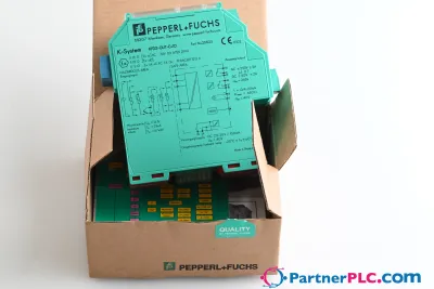 NewPepperl + Fuchs KFD2-GUT-EX1.D New open box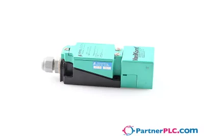
 Available on requestPepperl Fuchs V19-W-BK15M-PUR-U-V19-G
 Available on requestPepperl Fuchs V1SD-G-GN65M-PUR-E1S-V45-G