


Pepperl Fuchs KFU8-SR-Ex1.W.LB
Request a Quote



Quick facts
| Availability | Confirmed on request |
| Category | K-System (DIN Rail Mounting) |
| Lifecycle | active |
| Warranty | 12-month (new) · 3-month (used/refurbished) |
Shipping & availability
When can KFU8-SR-Ex1.W.LB be shipped?
KFU8-SR-Ex1.W.LB is sourced on request — request a quote and we'll confirm the exact availability and shipping timeline for this specific unit.
Can I pick up KFU8-SR-Ex1.W.LB in person?
Local pickup from our Groningen, Netherlands warehouse may be possible — contact us before ordering to check availability and arrange a collection time.
Is express delivery available?
Yes — mention it when you request a quote for KFU8-SR-Ex1.W.LB and we'll include express shipping options in our reply.
My factory is down and I need this urgently — can you help?
For a critical breakdown, contact us directly at +31 (0)50-7110348 or sales@partnerplc.com — we can look into same-day courier or dedicated taxi/hotshot delivery for KFU8-SR-Ex1.W.LB, subject to availability and destination.
Switch Amplifier. 1-channel isolated barrier, Universal usage at different power supplies, Dry contact or NAMUR inputs, Relay contact output, Fault relay contact output, Line fault detection (LFD), Reversible mode of operation, Up to SIL 2 (SC 3) acc. to IEC/EN 61508, Housing width: 20 mm, Number of channels: 1-channel, Safety Integrity Level (SIL): SIL 2, Systematic capability (SC): SC 3, Rated voltage: 19 ... 30 V DC / 90 ... 253 V AC 50 ... 60 Hz, Field device: NAMUR sensor, Field device [2]: volt-free contact. Signal type: Digital Input. Safety Integrity Level (SIL): SIL 2. Systematic capability (SC): SC 3. Connection: terminals 14, 15. Rated voltage: 19 ... 30 V DC / 90 ... 253 V AC 50 ... 60 Hz. Power dissipation/power consumption: ≤ 1.2 W / ≤ 1.2 W ; 3.4 VA. Connection side: field side. Connection: terminals 1+, 2+, 3-. Rated values: acc. to EN 60947-5-6 (NAMUR). Open circuit voltage/short-circuit current: approx. 8 V DC / approx. 8 mA. Switching point/switching hysteresis: 1.2 ... 2.1 mA / approx. 0.2 mA. Line fault detection: breakage I ≤ 0.1 mA , short-circuit I > 6 mA. Pulse/Pause ratio: min. 20 ms / min. 20 ms. Connection side: control side. Connection: output I: terminals 7, 8, 9 ; output II: terminals 10, 11, 12. Output I: signal ; relay. Output II: signal or fault message ; relay. Contact loading: 250 V AC/2 A/cos φ > 0.75; 126.5 V AC/4 A/cos φ > 0.75; 40 V DC/2 A resistive load. Minimum switch current: 2 mA / 24 V DC. Energized/De-energized delay: approx. 20 ms / approx. 20 ms. Mechanical life: 107 switching cycles. Switching frequency: ≤ 10 Hz. Input/Output: reinforced insulation according to IEC/EN 61010-1, rated insulation voltage 300 Veff. Input/power supply: reinforced insulation according to IEC/EN 61010-1, rated insulation voltage 300 Veff. Output/power supply: reinforced insulation according to IEC/EN 61010-1, rated insulation voltage 300 Veff. Output/Output: reinforced insulation according to IEC/EN 61010-1, rated insulation voltage 300 Veff. Display elements: LEDs. Control elements: DIP switch. Configuration: via DIP switches. Labeling: space for labeling at the front. Electromagnetic compatibility: . Directive 2014/30/EUEN 61326-1:2013 (industrial locations): . Directive 2014/30/EU: EN 61326-1:2013 (industrial locations). Low voltage: . Directive 2014/35/EUEN 61010-1:2010+A1:2019+A1:2019/AC:2019: . Directive 2014/35/EU: EN 61010-1:2010+A1:2019+A1:2019/AC:2019. Electromagnetic compatibility: NE 21:2017 , EN 61326-3-1:2017 , EN IEC 61326-3-2:2018 , EN IEC 61326-1:2021 (industrial locations). Degree of protection: IEC 60529:1989+A1:1999+A2:2013. Input: EN 60947-5-6:2000. Ambient temperature: -40 ... 60 °C (-40 ... 140 °F) extended ambient temperature range up to 70 °C (158 °F), refer to manual for necessary mounting conditions. Degree of protection: IP20. Connection: screw terminals. Mass: approx. 150 g. Dimensions: 20 x 119 x 115 mm (0.8 x 4.7 x 4.5 inch) (W x H x D) , housing type B2. Height119 mmWidth20 mmDepth115 mm: . Height: 119 mm. Width: 20 mm. Depth: 115 mm. Mounting: on 35 mm DIN mounting rail acc. to EN 60715:2001. EU-type examination certificate: FIDI 22 ATEX 0029 X. Marking II 3(1)G Ex ec nC [ia Ga] IIC T4 Gc [exsign] II (1)D [Ex ia Da] IIIC [exsign] I (M1) [Ex ia Ma] IInputEx iaVoltageUo10.5 VCurrentIo13 mAPowerPo34 mW (linear characteristic): . Marking: II 3(1)G Ex ec nC [ia Ga] IIC T4 Gc [exsign] II (1)D [Ex ia Da] IIIC [exsign] I (M1) [Ex ia Ma] I. Input: Ex ia. Voltage: 10.5 V. Current: 13 mA. Power: 34 mW (linear characteristic). Supply: . Maximum safe voltageUm253 V AC (Attention! Um is no rated voltage.): Um. Maximum safe voltage: 253 V AC (Attention! Um is no rated voltage.). Output: . Maximum safe voltageUm253 V AC (Attention! The rated voltage can be lower.): Um. Maximum safe voltage: 253 V AC (Attention! The rated voltage can be lower.). Galvanic isolation: . Input/Outputsafe electrical isolation acc. to IEC/EN 60079-11, voltage peak value 375 VInput/power supplysafe electrical isolation acc. to IEC/EN 60079-11, voltage peak value 375 V: . Input/Output: safe electrical isolation acc. to IEC/EN 60079-11, voltage peak value 375 V. Input/power supply: safe electrical isolation acc. to IEC/EN 60079-11, voltage peak value 375 V. Directive conformity: . Directive 2014/34/EUEN IEC 60079-0:2018 , EN 60079-7:2015+A1:2018 , EN 60079-11:2012 , EN IEC 60079-15:2019: . Directive 2014/34/EU: EN IEC 60079-0:2018 , EN 60079-7:2015+A1:2018 , EN 60079-11:2012 , EN IEC 60079-15:2019. UL approval: E106378. Control drawing116-0489Contact loading250 V AC/2 A/cos φ > 0.75; 126.5 V AC/4 A/cos φ > 0.75; 30 V DC/2 A resistive load: . Control drawing: 116-0489. Contact loading: 250 V AC/2 A/cos φ > 0.75; 126.5 V AC/4 A/cos φ > 0.75; 30 V DC/2 A resistive load. IECEx approval: . IECEx certificateIECEx FIDI 22.0003XIECEx markingEx ec nC [ia Ga] IIC T4 Gc , [Ex ia Da] IIIC , [Ex ia Ma] I: . IECEx certificate: IECEx FIDI 22.0003X. IECEx marking: Ex ec nC [ia Ga] IIC T4 Gc , [Ex ia Da] IIIC , [Ex ia Ma] I. Supplementary information: Observe the certificates, declarations of conformity, instruction manuals, and manuals where applicable. For information see www.pepperl-fuchs.com.
Specifications
General specifications
| Signal type | Digital Input |
Functional safety related parameters
| Safety Integrity Level (SIL) | SIL 2 |
| Systematic capability (SC) | SC 3 |
Supply
| Connection | terminals 14, 15 |
| Rated voltage | 19 ... 30 V DC / 90 ... 253 V AC 50 ... 60 Hz Ur |
| Power dissipation/power consumption | ≤ 1.2 W / ≤ 1.2 W ; 3.4 VA |
Input
| Connection side | field side |
| Connection | terminals 1+, 2+, 3- |
| Rated values | acc. to EN 60947-5-6 (NAMUR) |
| Open circuit voltage/short-circuit current | approx. 8 V DC / approx. 8 mA |
| Switching point/switching hysteresis | 1.2 ... 2.1 mA / approx. 0.2 mA |
| Line fault detection | breakage I ≤ 0.1 mA , short-circuit I > 6 mA |
| Pulse/Pause ratio | min. 20 ms / min. 20 ms |
Output
| Connection side | control side |
| Connection | output I: terminals 7, 8, 9 ; output II: terminals 10, 11, 12 |
| Output I | signal ; relay |
| Output II | signal or fault message ; relay |
| Contact loading | 250 V AC/2 A/cos φ > 0.75; 126.5 V AC/4 A/cos φ > 0.75; 40 V DC/2 A resistive load |
| Minimum switch current | 2 mA / 24 V DC |
| Energized/De-energized delay | approx. 20 ms / approx. 20 ms |
| Mechanical life | 107 switching cycles |
Transfer characteristics
| Switching frequency | ≤ 10 Hz |
Galvanic isolation
| Input/Output | reinforced insulation according to IEC/EN 61010-1, rated insulation voltage 300 Veff |
| Input/power supply | reinforced insulation according to IEC/EN 61010-1, rated insulation voltage 300 Veff |
| Output/power supply | reinforced insulation according to IEC/EN 61010-1, rated insulation voltage 300 Veff |
| Output/Output | reinforced insulation according to IEC/EN 61010-1, rated insulation voltage 300 Veff |
Indicators/settings
| Display elements | LEDs |
| Control elements | DIP switch |
| Configuration | via DIP switches |
| Labeling | space for labeling at the front |
Directive conformity
| Electromagnetic compatibility | |
| Directive 2014/30/EUEN 61326-1:2013 (industrial locations) | Directive 2014/30/EU |
| Directive 2014/30/EU | EN 61326-1:2013 (industrial locations) |
| Low voltage | |
| Directive 2014/35/EUEN 61010-1:2010+A1:2019+A1:2019/AC:2019 | Directive 2014/35/EU |
| Directive 2014/35/EU | EN 61010-1:2010+A1:2019+A1:2019/AC:2019 |
Conformity
| Electromagnetic compatibility | NE 21:2017 , EN 61326-3-1:2017 , EN IEC 61326-3-2:2018 , EN IEC 61326-1:2021 (industrial locations) |
| Degree of protection | IEC 60529:1989+A1:1999+A2:2013 |
| Input | EN 60947-5-6:2000 |
Ambient conditions
| Ambient temperature | -40 ... 60 °C (-40 ... 140 °F) extended ambient temperature range up to 70 °C (158 °F), refer to manual for necessary mounting conditions |
Mechanical specifications
| Degree of protection | IP20 |
| Connection | screw terminals |
| Mass | approx. 150 g |
| Dimensions | 20 x 119 x 115 mm (0.8 x 4.7 x 4.5 inch) (W x H x D) , housing type B2 |
| Height119 mmWidth20 mmDepth115 mm | Height |
| Height | 119 mm |
| Width | 20 mm |
| Depth | 115 mm |
| Mounting | on 35 mm DIN mounting rail acc. to EN 60715:2001 |
Data for application in connection with hazardous areas
| EU-type examination certificate | FIDI 22 ATEX 0029 X |
| Marking II 3(1)G Ex ec nC [ia Ga] IIC T4 Gc [exsign] II (1)D [Ex ia Da] IIIC [exsign] I (M1) [Ex ia Ma] IInputEx iaVoltageUo10.5 VCurrentIo13 mAPowerPo34 mW (linear characteristic) | Marking |
| Marking | II 3(1)G Ex ec nC [ia Ga] IIC T4 Gc [exsign] II (1)D [Ex ia Da] IIIC [exsign] I (M1) [Ex ia Ma] I |
| Input | Ex ia |
| Voltage | 10.5 V Uo |
| Current | 13 mA Io |
| Power | 34 mW (linear characteristic) Po |
| Supply | |
| Maximum safe voltageUm253 V AC (Attention! Um is no rated voltage.) | Um Maximum safe voltage |
| Maximum safe voltage | 253 V AC (Attention! Um is no rated voltage.) Um |
| Output | |
| Maximum safe voltageUm253 V AC (Attention! The rated voltage can be lower.) | Um Maximum safe voltage |
| Maximum safe voltage | 253 V AC (Attention! The rated voltage can be lower.) Um |
| Galvanic isolation | |
| Input/Outputsafe electrical isolation acc. to IEC/EN 60079-11, voltage peak value 375 VInput/power supplysafe electrical isolation acc. to IEC/EN 60079-11, voltage peak value 375 V | Input/Output |
| Input/Output | safe electrical isolation acc. to IEC/EN 60079-11, voltage peak value 375 V |
| Input/power supply | safe electrical isolation acc. to IEC/EN 60079-11, voltage peak value 375 V |
| Directive conformity | |
| Directive 2014/34/EUEN IEC 60079-0:2018 , EN 60079-7:2015+A1:2018 , EN 60079-11:2012 , EN IEC 60079-15:2019 | Directive 2014/34/EU |
| Directive 2014/34/EU | EN IEC 60079-0:2018 , EN 60079-7:2015+A1:2018 , EN 60079-11:2012 , EN IEC 60079-15:2019 |
International approvals
| UL approval | E106378 |
| Control drawing116-0489Contact loading250 V AC/2 A/cos φ > 0.75; 126.5 V AC/4 A/cos φ > 0.75; 30 V DC/2 A resistive load | Control drawing |
| Control drawing | 116-0489 |
| Contact loading | 250 V AC/2 A/cos φ > 0.75; 126.5 V AC/4 A/cos φ > 0.75; 30 V DC/2 A resistive load |
| IECEx approval | |
| IECEx certificateIECEx FIDI 22.0003XIECEx markingEx ec nC [ia Ga] IIC T4 Gc , [Ex ia Da] IIIC , [Ex ia Ma] I | IECEx certificate |
| IECEx certificate | IECEx FIDI 22.0003X |
| IECEx marking | Ex ec nC [ia Ga] IIC T4 Gc , [Ex ia Da] IIIC , [Ex ia Ma] I |
General information
| Supplementary information | Observe the certificates, declarations of conformity, instruction manuals, and manuals where applicable. For information see www.pepperl-fuchs.com. |
More Pepperl Fuchs parts
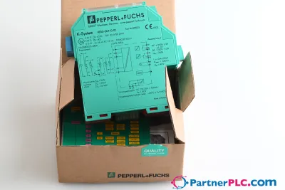 NewPepperl + Fuchs KFD2-GUT-EX1.D New open box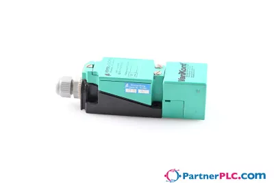
 Available on requestPepperl Fuchs V19-W-BK15M-PUR-U-V19-G
 Available on requestPepperl Fuchs V1SD-G-GN65M-PUR-E1S-V45-G