


Pepperl Fuchs KFD2-RCI-1
Request a Quote



Quick facts
| Availability | Confirmed on request |
| Category | K-System (DIN Rail Mounting, Highly Functional) |
| Lifecycle | active |
| Warranty | 12-month (new) · 3-month (used/refurbished) |
Shipping & availability
When can KFD2-RCI-1 be shipped?
KFD2-RCI-1 is sourced on request — request a quote and we'll confirm the exact availability and shipping timeline for this specific unit.
Can I pick up KFD2-RCI-1 in person?
Local pickup from our Groningen, Netherlands warehouse may be possible — contact us before ordering to check availability and arrange a collection time.
Is express delivery available?
Yes — mention it when you request a quote for KFD2-RCI-1 and we'll include express shipping options in our reply.
My factory is down and I need this urgently — can you help?
For a critical breakdown, contact us directly at +31 (0)50-7110348 or sales@partnerplc.com — we can look into same-day courier or dedicated taxi/hotshot delivery for KFD2-RCI-1, subject to availability and destination.
Solenoid Driver. 1-channel signal conditioner, 24 V DC supply (Power Rail), Output 20.4 mA at 13.5 V DC, 19 V DC ... 30 V DC input, Test pulse immunity, Line fault detection (LFD), Up to SIL 3 acc. to IEC/EN 61508, Housing width: 20 mm, Number of channels: 1-channel, Conformal coating, Safety Integrity Level (SIL): SIL 3, Rated voltage: 19 ... 30 V DC, Type: logic input, Field device: 1 x Valve, Field device [2]: 1 x audible alarm, Field device [3]: 1 x visual alarm, Fault indication output, Line fault detection. Signal type: Digital Output. Safety Integrity Level (SIL): SIL 3. Connection: Power Rail or terminals 14+, 15-. Rated voltage: 19 ... 30 V DC. Rated current: < 35 mA. Power consumption: < 0.8 W. Connection side: control side. Connection: terminals 10+, 11-. Test pulse length: max. 2 ms from DO card. Input current: 40 mA at 19 ... 30 V DC. Signal level: 1-signal: 19 ... 30 V DC 0-signal: 0 ... 5 V DC. Power consumption: < 1.2 W. Operating mode: loop powered. Connection side: field side/control side. Connection: terminals 1+, 3- (terminals 1+, 2 for test loop). Internal resistor: approx. 275 Ω. Current: ≤ 20.4 mA. Voltage: ≥ 13.5 V. Open loop voltage: > 16 V. Voltage: 1-signal: > 13.5 V. Current: 1-signal: 20.4 A 0-signal: 4.2 mA. Load: max. 650 Ω. Response time: < 40 ms input to output. Line fault detection: short circuit voltage < 1 V , open circuit voltage > 16 V. Output II: . Connectionterminal 7: source (-) or sink (+), terminal 8: source (+), terminal 9: sink (-)Current11 mA (source or sink mode)Voltage9 ... 30 V sink mode from external supplyLoadmax. 650 Ω , source mode , for HART ≥ 230 ΩCommunicationpass-through of HART signal between input II and output: . Connection: terminal 7: source (-) or sink (+), terminal 8: source (+), terminal 9: sink (-). Current: 11 mA (source or sink mode). Voltage: 9 ... 30 V sink mode from external supply. Load: max. 650 Ω , source mode , for HART ≥ 230 Ω. Communication: pass-through of HART signal between input II and output. Field circuit/control circuit: basic insulation according to IEC 61010-1, rated insulation voltage 300 Veff. Input/power supply: functional insulation, rated insulation voltage 50 Veff. Output II/power supply: functional insulation, rated insulation voltage 50 Veff. Display elements: LEDs. Control elements: DIP switch. Configuration: via DIP switches. Labeling: space for labeling at the front. Electromagnetic compatibility: . Directive 2014/30/EUEN 61326-1:2013 (industrial locations): . Directive 2014/30/EU: EN 61326-1:2013 (industrial locations). Electromagnetic compatibility: NE 21:2012. Degree of protection: IEC 60529:2001. Ambient temperature: -20 ... 60 °C (-4 ... 140 °F). Degree of protection: IP20. Connection: screw terminals. Mass: approx. 150 g. Dimensions: 20 x 119 x 115 mm (0.8 x 4.7 x 4.5 inch) (W x H x D) , housing type B2. Height119 mmWidth20 mmDepth115 mm: . Height: 119 mm. Width: 20 mm. Depth: 115 mm. Mounting: on 35 mm DIN mounting rail acc. to EN 60715:2001. Supplementary information: Observe the certificates, declarations of conformity, instruction manuals, and manuals where applicable. For information see www.pepperl-fuchs.com.
Specifications
General specifications
| Signal type | Digital Output |
Functional safety related parameters
| Safety Integrity Level (SIL) | SIL 3 |
Supply
| Connection | Power Rail or terminals 14+, 15- |
| Rated voltage | 19 ... 30 V DC Ur |
| Rated current | < 35 mA Ir |
| Power consumption | < 0.8 W |
Input
| Connection side | control side |
| Connection | terminals 10+, 11- |
| Test pulse length | max. 2 ms from DO card |
| Input current | 40 mA at 19 ... 30 V DC |
| Signal level | 1-signal: 19 ... 30 V DC 0-signal: 0 ... 5 V DC |
| Power consumption | < 1.2 W |
| Operating mode | loop powered |
Output
| Connection side | field side/control side |
| Connection | terminals 1+, 3- (terminals 1+, 2 for test loop) |
| Internal resistor | approx. 275 Ω Ri |
| Current | ≤ 20.4 mA Ie |
| Voltage | ≥ 13.5 V Ue |
| Open loop voltage | > 16 V Us |
| Voltage | 1-signal: > 13.5 V |
| Current | 1-signal: 20.4 A 0-signal: 4.2 mA |
| Load | max. 650 Ω |
| Response time | < 40 ms input to output |
| Line fault detection | short circuit voltage < 1 V , open circuit voltage > 16 V |
| Output II | |
| Connectionterminal 7: source (-) or sink (+), terminal 8: source (+), terminal 9: sink (-)Current11 mA (source or sink mode)Voltage9 ... 30 V sink mode from external supplyLoadmax. 650 Ω , source mode , for HART ≥ 230 ΩCommunicationpass-through of HART signal between input II and output | Connection |
| Connection | terminal 7: source (-) or sink (+), terminal 8: source (+), terminal 9: sink (-) |
| Current | 11 mA (source or sink mode) |
| Voltage | 9 ... 30 V sink mode from external supply |
| Load | max. 650 Ω , source mode , for HART ≥ 230 Ω |
| Communication | pass-through of HART signal between input II and output |
Galvanic isolation
| Field circuit/control circuit | basic insulation according to IEC 61010-1, rated insulation voltage 300 Veff |
| Input/power supply | functional insulation, rated insulation voltage 50 Veff |
| Output II/power supply | functional insulation, rated insulation voltage 50 Veff |
Indicators/settings
| Display elements | LEDs |
| Control elements | DIP switch |
| Configuration | via DIP switches |
| Labeling | space for labeling at the front |
Directive conformity
| Electromagnetic compatibility | |
| Directive 2014/30/EUEN 61326-1:2013 (industrial locations) | Directive 2014/30/EU |
| Directive 2014/30/EU | EN 61326-1:2013 (industrial locations) |
Conformity
| Electromagnetic compatibility | NE 21:2012 |
| Degree of protection | IEC 60529:2001 |
Ambient conditions
| Ambient temperature | -20 ... 60 °C (-4 ... 140 °F) |
Mechanical specifications
| Degree of protection | IP20 |
| Connection | screw terminals |
| Mass | approx. 150 g |
| Dimensions | 20 x 119 x 115 mm (0.8 x 4.7 x 4.5 inch) (W x H x D) , housing type B2 |
| Height119 mmWidth20 mmDepth115 mm | Height |
| Height | 119 mm |
| Width | 20 mm |
| Depth | 115 mm |
| Mounting | on 35 mm DIN mounting rail acc. to EN 60715:2001 |
General information
| Supplementary information | Observe the certificates, declarations of conformity, instruction manuals, and manuals where applicable. For information see www.pepperl-fuchs.com. |
More Pepperl Fuchs parts
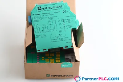 NewPepperl + Fuchs KFD2-GUT-EX1.D New open box
 Available on requestPepperl Fuchs V19-W-BK15M-PUR-U-V19-G
 Available on requestPepperl Fuchs V1SD-G-GN65M-PUR-E1S-V45-G