


Pepperl Fuchs FB5205B3
Request a Quote



Quick facts
| Availability | Confirmed on request |
| Category | FB (Zone 1) |
| Lifecycle | active |
| Warranty | 12-month (new) · 3-month (used/refurbished) |
Shipping & availability
When can FB5205B3 be shipped?
FB5205B3 is sourced on request — request a quote and we'll confirm the exact availability and shipping timeline for this specific unit.
Can I pick up FB5205B3 in person?
Local pickup from our Groningen, Netherlands warehouse may be possible — contact us before ordering to check availability and arrange a collection time.
Is express delivery available?
Yes — mention it when you request a quote for FB5205B3 and we'll include express shipping options in our reply.
My factory is down and I need this urgently — can you help?
For a critical breakdown, contact us directly at +31 (0)50-7110348 or sales@partnerplc.com — we can look into same-day courier or dedicated taxi/hotshot delivery for FB5205B3, subject to availability and destination.
Thermocouple Converter. 4-channel, Inputs Ex ia, Installation in suitable enclosures in Zone 1, Module can be exchanged under voltage (hot swap), Explosion protection: Ex ia, Field device [2]: Thermocouple, Field device [4]: mV source. Occupied slots: 2. Connection: backplane bus. Rated voltage: 12 V DC , only in connection with the power supplies FB92**. Power dissipation: 0.75 W. Power consumption: 0.75 W. Connection: backplane bus. Interface: manufacturer-specific bus to standard com unit. Number of channels: 4. Suitable field devices: . Field device [2]ThermocoupleField device [4]mV source: . Field device [2]: Thermocouple. Field device [4]: mV source. Suitable sensors: . Sensorthermocouples U, B, E, T, K, S, R, L, J, N, Pallaplat and mV sources: . Sensor: thermocouples U, B, E, T, K, S, R, L, J, N, Pallaplat and mV sources. Connection: channel I: 1+, 2-; channel II: 5+, 6-; channel III: 9+, 10-; channel IV: 13+, 14-. Measuring range: -65 ... 75 mV with LFD , -75 ... 75 mV without LFD. Smallest span: 5 mV for 0.1 % accuracy. Linearity error: 0.1 %. Conversion time: max. 300 ms (4 channels) without LFD max. 600 ms (4-channel) with LFD. Compensation (reference junction CJC): internal cold junction compensation or external cold junction. Line fault detection: can be switched on/off for each channel via configuration tool ,. Open-circuit> 1 kΩ: . Open-circuit: > 1 kΩ. Deviation: . Influence of ambient temperaturemax. 0,1 %/10 K: . Influence of ambient temperature: max. 0,1 %/10 K. LED indication: LED green: supply LED red: line fault, collective alarm , flashing: communication error. Coding: optional mechanical coding via front socket. Electromagnetic compatibility: . Directive 2014/30/EUEN 61326-1:2013: . Directive 2014/30/EU: EN 61326-1:2013. Electromagnetic compatibility: NE 21. Degree of protection: IEC 60529. Environmental test: EN 60068-2-14. Shock resistance: EN 60068-2-27. Vibration resistance: EN 60068-2-6. Damaging gas: EN 60068-2-42. Relative humidity: EN 60068-2-78. Ambient temperature: -40 ... 60 °C (-40 ... 140 °F). Storage temperature: -40 ... 85 °C (-40 ... 185 °F). Relative humidity: 95 % non-condensing. Shock resistance: shock type I, shock duration 11 ms, shock amplitude 15 g, number of shocks 18. Vibration resistance: frequency range 10 ... 150 Hz; transition frequency: 57.56 Hz, amplitude/acceleration ± 0.075 mm/1 g; 10 cyclesfrequency range 5 ... 100 Hz; transition frequency: 13.2 Hz amplitude/acceleration ± 1 mm/0.7 g; 90 minutes at each resonance. Damaging gas: designed for operation in environmental conditions acc. to ISA-S71.04-1985, severity level G3. Degree of protection: IP20 (module) , a separate housing is required acc. to the system description. Connection: removable front connector with screw flange (accessory)wiring connection via spring terminals (0.14 ... 1.5 mm2) or screw terminals (0.08 ... 1.5 mm2). Mass: approx. 955 g. Dimensions: . Height107 mmWidth57 mmDepth132 mm: . Height: 107 mm. Width: 57 mm. Depth: 132 mm. EU-type examination certificate: Presafe 19 ATEX 14058U. Marking II 2(1)G Ex db eb q [ia Ga] IIC Gb II (1)D [Ex ia Da] IIIC I (M1) [Ex ia Ma] I: . Marking: II 2(1)G Ex db eb q [ia Ga] IIC Gb II (1)D [Ex ia Da] IIIC I (M1) [Ex ia Ma] I. Input: . VoltageUo1 VCurrentIo71 mAPowerPo62 mW (trapezoid characteristic curve): Uo. Voltage: 1 V. Current: 71 mA. Power: 62 mW (trapezoid characteristic curve). Galvanic isolation: . Input/inputfunctional insulation acc. to IEC 60664-1:2007, rated insulation voltage 50 V, testing voltage 500 VInput/power supply, internal bussafe electrical isolation acc. to EN 60079-11, voltage peak value 375 V: . Input/input: functional insulation acc. to IEC 60664-1:2007, rated insulation voltage 50 V, testing voltage 500 V. Input/power supply, internal bus: safe electrical isolation acc. to EN 60079-11, voltage peak value 375 V. Directive conformity: . Directive 2014/34/EUEN IEC 60079-0:2018+AC:2020 EN 60079-1:2014 EN 60079-5:2015 EN 60079-7:2015+A1:2018 EN 60079-11:2012: . Directive 2014/34/EU: EN IEC 60079-0:2018+AC:2020 EN 60079-1:2014 EN 60079-5:2015 EN 60079-7:2015+A1:2018 EN 60079-11:2012. ATEX approval: Presafe 19 ATEX 14058U. IECEx approval: . IECEx certificateIECEx PRE 19.0013UIECEx markingEx db eb q [ia Ga] IIC Gb [Ex ia Da] IIIC [Ex ia Ma] I: . IECEx certificate: IECEx PRE 19.0013U. IECEx marking: Ex db eb q [ia Ga] IIC Gb [Ex ia Da] IIIC [Ex ia Ma] I. System information: The module has to be mounted in appropriate backplanes and housings (FB92**) in Zone 1, 2, 21, 22 or outside hazardous areas (gas or dust). Here, observe the corresponding EC-type examination certificate.. Supplementary information: EC-Type Examination Certificate, Statement of Conformity, Declaration of Conformity, Attestation of Conformity and instructions have to be observed where applicable. For information see www.pepperl-fuchs.com.
Specifications
Slots
| Occupied slots | 2 |
Supply
| Connection | backplane bus |
| Rated voltage | 12 V DC , only in connection with the power supplies FB92** Ur |
| Power dissipation | 0.75 W |
| Power consumption | 0.75 W |
Internal bus
| Connection | backplane bus |
| Interface | manufacturer-specific bus to standard com unit |
temperature input
| Number of channels | 4 |
| Suitable field devices | |
| Field device [2]ThermocoupleField device [4]mV source | Field device [2] |
| Field device [2] | Thermocouple |
| Field device [4] | mV source |
| Suitable sensors | |
| Sensorthermocouples U, B, E, T, K, S, R, L, J, N, Pallaplat and mV sources | Sensor |
| Sensor | thermocouples U, B, E, T, K, S, R, L, J, N, Pallaplat and mV sources |
| Connection | channel I: 1+, 2-; channel II: 5+, 6-; channel III: 9+, 10-; channel IV: 13+, 14- |
| Measuring range | -65 ... 75 mV with LFD , -75 ... 75 mV without LFD |
| Smallest span | 5 mV for 0.1 % accuracy |
| Linearity error | 0.1 % |
| Conversion time | max. 300 ms (4 channels) without LFD max. 600 ms (4-channel) with LFD |
| Compensation (reference junction CJC) | internal cold junction compensation or external cold junction |
| Line fault detection | can be switched on/off for each channel via configuration tool , |
| Open-circuit> 1 kΩ | Open-circuit |
| Open-circuit | > 1 kΩ |
Transfer characteristics
| Deviation | |
| Influence of ambient temperaturemax. 0,1 %/10 K | Influence of ambient temperature |
| Influence of ambient temperature | max. 0,1 %/10 K |
Indicators/settings
| LED indication | LED green: supply LED red: line fault, collective alarm , flashing: communication error |
| Coding | optional mechanical coding via front socket |
Directive conformity
| Electromagnetic compatibility | |
| Directive 2014/30/EUEN 61326-1:2013 | Directive 2014/30/EU |
| Directive 2014/30/EU | EN 61326-1:2013 |
Conformity
| Electromagnetic compatibility | NE 21 |
| Degree of protection | IEC 60529 |
| Environmental test | EN 60068-2-14 |
| Shock resistance | EN 60068-2-27 |
| Vibration resistance | EN 60068-2-6 |
| Damaging gas | EN 60068-2-42 |
| Relative humidity | EN 60068-2-78 |
Ambient conditions
| Ambient temperature | -40 ... 60 °C (-40 ... 140 °F) |
| Storage temperature | -40 ... 85 °C (-40 ... 185 °F) |
| Relative humidity | 95 % non-condensing |
| Shock resistance | shock type I, shock duration 11 ms, shock amplitude 15 g, number of shocks 18 |
| Vibration resistance | frequency range 10 ... 150 Hz; transition frequency: 57.56 Hz, amplitude/acceleration ± 0.075 mm/1 g; 10 cyclesfrequency range 5 ... 100 Hz; transition frequency: 13.2 Hz amplitude/acceleration ± 1 mm/0.7 g; 90 minutes at each resonance |
| Damaging gas | designed for operation in environmental conditions acc. to ISA-S71.04-1985, severity level G3 |
Mechanical specifications
| Degree of protection | IP20 (module) , a separate housing is required acc. to the system description |
| Connection | removable front connector with screw flange (accessory)wiring connection via spring terminals (0.14 ... 1.5 mm2) or screw terminals (0.08 ... 1.5 mm2) |
| Mass | approx. 955 g |
| Dimensions | |
| Height107 mmWidth57 mmDepth132 mm | Height |
| Height | 107 mm |
| Width | 57 mm |
| Depth | 132 mm |
Data for application in connection with hazardous areas
| EU-type examination certificate | Presafe 19 ATEX 14058U |
| Marking II 2(1)G Ex db eb q [ia Ga] IIC Gb II (1)D [Ex ia Da] IIIC I (M1) [Ex ia Ma] I | Marking |
| Marking | II 2(1)G Ex db eb q [ia Ga] IIC Gb II (1)D [Ex ia Da] IIIC I (M1) [Ex ia Ma] I |
| Input | |
| VoltageUo1 VCurrentIo71 mAPowerPo62 mW (trapezoid characteristic curve) | Uo Voltage |
| Voltage | 1 V Uo |
| Current | 71 mA Io |
| Power | 62 mW (trapezoid characteristic curve) Po |
| Galvanic isolation | |
| Input/inputfunctional insulation acc. to IEC 60664-1:2007, rated insulation voltage 50 V, testing voltage 500 VInput/power supply, internal bussafe electrical isolation acc. to EN 60079-11, voltage peak value 375 V | Input/input |
| Input/input | functional insulation acc. to IEC 60664-1:2007, rated insulation voltage 50 V, testing voltage 500 V |
| Input/power supply, internal bus | safe electrical isolation acc. to EN 60079-11, voltage peak value 375 V |
| Directive conformity | |
| Directive 2014/34/EUEN IEC 60079-0:2018+AC:2020 EN 60079-1:2014 EN 60079-5:2015 EN 60079-7:2015+A1:2018 EN 60079-11:2012 | Directive 2014/34/EU |
| Directive 2014/34/EU | EN IEC 60079-0:2018+AC:2020 EN 60079-1:2014 EN 60079-5:2015 EN 60079-7:2015+A1:2018 EN 60079-11:2012 |
International approvals
| ATEX approval | Presafe 19 ATEX 14058U |
| IECEx approval | |
| IECEx certificateIECEx PRE 19.0013UIECEx markingEx db eb q [ia Ga] IIC Gb [Ex ia Da] IIIC [Ex ia Ma] I | IECEx certificate |
| IECEx certificate | IECEx PRE 19.0013U |
| IECEx marking | Ex db eb q [ia Ga] IIC Gb [Ex ia Da] IIIC [Ex ia Ma] I |
General information
| System information | The module has to be mounted in appropriate backplanes and housings (FB92**) in Zone 1, 2, 21, 22 or outside hazardous areas (gas or dust). Here, observe the corresponding EC-type examination certificate. |
| Supplementary information | EC-Type Examination Certificate, Statement of Conformity, Declaration of Conformity, Attestation of Conformity and instructions have to be observed where applicable. For information see www.pepperl-fuchs.com. |
More Pepperl Fuchs parts
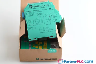 NewPepperl + Fuchs KFD2-GUT-EX1.D New open box
 Available on requestPepperl Fuchs V19-W-BK15M-PUR-U-V19-G
 Available on requestPepperl Fuchs V1SD-G-GN65M-PUR-E1S-V45-G