
B&R X90CP174.48-00 – Interfaces, 1x Ethernet, 1x USB, 3x CAN bus, 1x POWERLINK
Request a Quote



Quick facts
| Availability | Confirmed on request |
| Category | X90 mobile control |
| Lifecycle | Active |
| Warranty | 12-month (new) · 3-month (used/refurbished) |
Shipping & availability
When can X90CP174.48-00 be shipped?
X90CP174.48-00 is sourced on request — request a quote and we'll confirm the exact availability and shipping timeline for this specific unit.
Can I pick up X90CP174.48-00 in person?
Local pickup from our Groningen, Netherlands warehouse may be possible — contact us before ordering to check availability and arrange a collection time.
Is express delivery available?
Yes — mention it when you request a quote for X90CP174.48-00 and we'll include express shipping options in our reply.
My factory is down and I need this urgently — can you help?
For a critical breakdown, contact us directly at +31 (0)50-7110348 or sales@partnerplc.com — we can look into same-day courier or dedicated taxi/hotshot delivery for X90CP174.48-00, subject to availability and destination.
• Agricultural and forestry machines
• Construction equipment
• Municipal utility vehicles
• Stationary outdoor applications
• Powerful ARM CPU with 650 MHz
• Multifunction I/O channels
• Ethernet, POWERLINK, 3x CAN bus, USB
• Modular expansion
The heart of the X90 mobile system is a controller with a powerful ARM processor and up to 48 multifunction I/O channels. Basic features include connections for CAN, USB, Ethernet and the real-time POWERLINK bus system.
The extremely robust die-cast aluminum housing provides space for up to 4 additional expansion boards. These make it possible to add I/O channels or interfaces as well as specific functions such as condition monitoring.
Accessories
Optional accessories (18)
| X90AISG0.02-00 | Analog inputs — 9 to 32 VDC; 2 full-bridge strain gauge inputs; Data output rate configurable from 2.5 Hz to 7.5 kHz; Special operating modes (synchronous… |
| X90AO410.08-00 | Analog outputs — 9 to 32 VDC; 8 analog outputs or digital inputs; X2X Link The AO option board offers 8 additional analog outputs, each of which can be conf… |
| X90AO410.04-00 | Analog outputs — 9 to 32 VDC; 4 analog outputs or digital inputs; X2X Link The AO option board offers 4 additional analog outputs, each of which can be conf… |
| X90AC-BB.17-00 | BreakOut Box — X90 mobile 170, breakout box for development and tests |
| X90TB100.03-00 | CMC connector — X90 mobile 170, connector set for CMC header, with connector contacts and dummy plugs |
| X90IF7L0.05-00 | Communication modules — X90 mobile IF option board, 3x CAN, 2x LIN (master), configuration using software |
| X90IF730.04-00 | Communication modules — 3 CAN bus interfaces; Serial interface In addition to the existing interfaces on the mainboard, option boards for communication are availab… |
| X90IF720.04-00 | Communication modules — 3 CAN bus interfaces; Serial interface In addition to the existing interfaces on the mainboard, option boards for communication are availab… |
| X90DSI00.04-00 | Communication modules — 18 to 30 VDC; 4 IO-Link devices; 4 digital channels, can be used as inputs or outputs; Sensor/actuator power supply; NetTime timestamps: IO… |
| X90CM480.04-00 | Condition Monitoring — 4-channel vibration measurement and analysis module; 24-bit resolution at 51.562 kHz; IEPE power supply; Extensive characteristic value cal… |
| X90DI110.10-00 | Digital inputs — 9 to 32 VDC; 10 digital inputs; Sink or source circuit; Counter inputs 50 kHz; X2X Link The DI option board offers 10 additional digital in… |
| X90RO440.05-00 | Digital outputs — 9 to 32 VDC; 5 digital outputs; Switching current 2 A; 5 normally open contacts; Single-channel isolated outputs; X2X Link The relay option… |
| X90PO210.08-00 | Digital outputs — 9 to 32 VDC; 8 PWM outputs; 4 A per channel; Current measurement; Central cutoff; X2X Link The PWM option board offers 8 additional analog… |
| X90SM546.02-01 | Motor modules — X90 stepper motor module, with current reduction function, module power supply 15 to 32 VDC, 2 motor connections,4 A continuous current, 8… |
| X90RO440.04-S1 | Safe digital outputs — 9 to 32 VDC; 4 safe relay outputs; Output type "Relay"; Nominal output current 2x 2 A and 2x 4 A; Normally open contact; Single-channel iso… |
| X90AT910.08-00 | Temperature measurement — 9 to 32 VDC; 8 current, voltage, temperature or digital inputs or PWM outputs; Temperature measurement; X2X Link The AT option board offers… |
| X90AT910.04-00 | Temperature measurement — 9 to 32 VDC; 4 current, voltage, temperature or digital inputs or PWM outputs; Temperature measurement; X2X Link The AT option board offers… |
| X90CA100.02-00 | Wire harness — X90 mobile 170, wiring harness starter set for X90CP17x, 2 m, for CMC header |
Specifications
Short description
| Interfaces | 1x Ethernet, 1x USB, 3x CAN bus, 1x POWERLINK |
| System module | Controller |
General information
| Diagnostics – Module run/error | Yes, using LED status indicator and software |
| Diagnostics – CPU function | Yes, using LED status indicator |
| Diagnostics – Ethernet | Yes, using LED status indicator |
| Support – Controller redundancy | No |
| Support – Storage health data support | Yes |
| Support – ACOPOS support | Yes |
| Support – reACTION-capable I/O channels | No |
| Support – Visual Components support | Yes |
| Certifications – UN ECE-R10 | Yes |
| Certifications – CE | Yes |
| Certifications – UKCA | Yes |
| Certifications – CRA (Cyber Resilience Act) | In preparation |
| Insulation voltage for GND and housing | 500 V eff " data-placement="top" data-html="true" data-container="body" data-content="Connected to capacitors and 60 V VDR protective element."> |
| B&R ID code | 0xEB3F |
| Cooling | Fanless |
| Status indicators | Controller function, overtemperature, Ethernet, POWERLINK |
| Power consumption without interface module and USB | CPU at U e = 9 / 32 V: 3.3 / 3.9 W; I/O at U e = 9 / 32 V: 0.9 / 3.4 W |
Input power supply
| Input current – V_CPU | Max. 5 A |
| Input current – V_I/O | Max. 10 A per connection pin |
| Integrated protective function – V_CPU | No, required fuse 5 A slow-blow |
| Integrated protective function – V_I/O | No, required fuse 10 A slow-blow per connection pin |
| Input voltage | 9 to 32 VDC |
| Reset switching threshold | 6.8 V ±5% |
| Overvoltage | 48 V ≤5 minutes |
| Overvoltage protection | Load dump pulse A 202 V R i = 4 Ω " data-placement="top" data-html="true" data-container="body" data-content="V_CPU and V_I/O connected externally."> |
| Reverse polarity protection | -48 V ≤5 minutes |
Controller
| Processor – Data code | 32 kB |
| Processor – Program code | 32 kB |
| Processor – Type | ARM Cortex-A9 |
| Processor – Clock frequency | 650 MHz |
| Processor – L2 cache | 512 kB |
| Standard memory – RAM | 256 MB DDR3 SDRAM |
| Application memory – Guaranteed | 100 TB |
| Application memory – Results for 5 years | 54.8 GB/day |
| Application memory – Type | 1 GB flash memory |
| Application memory – Data retention | 10 years |
| Application memory – Guaranteed erase/write cycles | 100,000 |
| Application memory – Error-correcting code (ECC) | Yes |
| Real-time clock | Resolution 1 s, retention min. 48 hours, typ. 250 hours at 25°C, precision ±30 ppm over the entire temperature range |
| Floating point unit (FPU) | Yes |
| Integrated I/O processor | Processes I/O data points in the background |
| Option boards | 4 |
| Remanent variables | 32 kB FRAM, retention >10 years " data-placement="top" data-html="true" data-container="body" data-content="Configurable in Automation Studio."> |
| Shortest task class cycle time | 400 µs |
Interfaces
| Interface IF2 – Physical layer | 10BASE-T / 100BASE-TX |
| Interface IF2 – Half-duplex | Yes |
| Interface IF2 – Full-duplex | Yes |
| Interface IF2 – Autonegotiation | Yes |
| Interface IF2 – Auto-MDI/MDIX | Yes |
| Interface IF2 – Type | Ethernet |
| Interface IF2 – Variant | M12, D-coded |
| Interface IF2 – Line length | Max. 100 m between 2 stations (segment length) |
| Interface IF2 – Transfer rate | 10/100 Mbit/s |
| Interface IF3 – Physical layer | 100BASE-TX |
| Interface IF3 – Half-duplex | Yes |
| Interface IF3 – Full-duplex | No |
| Interface IF3 – Autonegotiation | Yes |
| Interface IF3 – Auto-MDI/MDIX | Yes |
| Interface IF3 – Fieldbus | POWERLINK managing or controlled node |
| Interface IF3 – Type | Type 6 " data-placement="top" data-html="true" data-container="body" data-content="For additional information, see section "Communication / POWERLINK / General information / Hardware - IF/LS" in Automation Help."> |
| Interface IF3 – Variant | M12, D-coded |
| Interface IF3 – Line length | Max. 100 m between 2 stations (segment length) |
| Interface IF3 – Transfer rate | 100 Mbit/s |
| Interface IF4 – Type | USB 1.1/2.0 |
| Interface IF4 – Variant | Type A (under service access window) |
| Interface IF4 – Max. output current | 500 mA |
| Interface IF7 – Connection designation | CAN1 |
| Interface IF7 – Type | CAN bus |
| Interface IF7 – Variant | Connection on CMC header X1.A |
| Interface IF7 – Max. distance | 1000 m |
| Interface IF7 – Transfer rate | Max. 1 Mbit/s |
| Interface IF7 – Terminating resistor | External 120 Ω must be provided. |
| Interface IF8 – Connection designation | CAN2 |
| Interface IF8 – Type | CAN bus |
| Interface IF8 – Variant | Connection on CMC header X1.A |
| Interface IF8 – Max. distance | 1000 m |
| Interface IF8 – Transfer rate | Max. 1 Mbit/s |
| Interface IF8 – Terminating resistor | External 120 Ω must be provided. |
| Interface IF9 – Connection designation | CAN3 |
| Interface IF9 – Type | CAN bus |
| Interface IF9 – Variant | Connection on CMC header X1.A |
| Interface IF9 – Max. distance | 1000 m |
| Interface IF9 – Transfer rate | Max. 1 Mbit/s |
| Interface IF9 – Terminating resistor | External 120 Ω must be provided. |
Multi-function inputs
| Multifunction digital inputs (MF-DI) – Quantity | 8 |
| Multifunction digital inputs (MF-DI) – Functions | Digital input: ; Sink/Source circuit - Configurable per channel, configurable software input filter, counter function up to 50 kHz counter frequency (AB, ABR, DF, edge counter), edge detection; with timestamp (for period duration, gate measurement, differential time measurement) |
| Multifunction analog inputs (MF-AI) – Quantity | 16 |
| Multifunction analog inputs (MF-AI) – Functions | Digital input (without diagnostics): ; Sink/Source circuit - Configurable per channel, configurable software input filter, fixed or ratiometrically configurable switching threshold; Digital input (with diagnostics): ; Configurable software input filter, open-circuit and short-circuit detection; Analog input: ; Measurement range 0 to 10 V / 0 to 32 V / 0 to 20 mA / 4 to 20 mA / 0 to 50 kΩ / temperature inputs (Pt1000 characteristic curve), configurable analog filter, configurable ramp limit, configurable threshold values, integrated input protection |
Multi-function outputs
| Multifunction digital outputs (MF-DO) – Quantity | 8 |
| Multifunction digital outputs (MF-DO) – Functions | Digital output: ; 4 A nominal current, source circuit, integrated output protection per channel, configurable overload monitoring per channel, central cutoff via relay, parallel connection, current measurement, error state with configurable error filter.; Digital input: ; Sink/Source circuit configurable per channel, configurable software input filter |
| Multifunction PWM outputs (MF-PWM) – Quantity | PWM 4 A: 11; PWM 6 A: 5 |
| Multifunction PWM outputs (MF-PWM) – Functions | Digital output: ; 4 A nominal current (PWM 4 A), 6 A nominal current (PWM 6 A), sink/source circuit, integrated; output protection per channel, configurable overload monitoring per channel, central cutoff; via relay, parallel connection, current measurement, error state with configurable error filter.; PWM output: ; 4 A nominal current (PWM 4 A), 6 A nominal current (PWM 6 A), PWM frequency 15 Hz to 4 kHz, ; sink/source circuit, integrated output protection per channel, configurable overload monitoring ; per channel, central cutoff via relay, parallel connection, current measurement (asynchronous or; synchronous to PWM period), configurable load current distribution of PWM outputs, dither.; H bridge: ; 4 A nominal current (PWM 4 A), 6 A nominal current (PWM 6 A), PWM frequency 15 Hz to 8 kHz (at load), integrated output protection per channel, configurable; overload monitoring per channel, central cutoff via relay, parallel connection, current measurement (asynchronous ; or synchronous to PWM period), configurable load current distribution of PWM outputs, dither.; Digital input: ; Sink/Source circuit configurable per channel, configurable software input filter |
Digital inputs
| Input filter – Hardware | MF-DI: 3 μs if switching threshold = 50% supply voltage; MF-AI: 300 μs if switching threshold = 50% supply voltage; MF-DO: 300 μs; MF-PWM: 150 μs |
| Input filter – Software | Default 1 ms, configurable between 0 and 25 ms in 0.1 ms increments |
| Quantity | 8 to 48, depends on the use of multifunction inputs/outputs |
| Nominal voltage | 12 / 24 VDC |
| Input voltage | 9 to 32 VDC |
| Input current at 24 VDC | MF-DI: Typ. 1.2 / 2.5 / 3.6 mA, configurable; MF-AI: Typ. 1.2 / 2.5 / 3.6 mA, configurable; MF-DO: Typ. 2.5 mA; MF-PWM: Typ. 2.5 mA " data-placement="top" data-html="true" data-container="body" data-content="Input current for MF-DI and MF-AI corresponds to the selected input resistance."> |
| Input circuit | Sink/Source, configurable |
| Input resistance | MF-AI and MF-DI: Typ. 6.5 / 9 / 18 kΩ, configurable; MF-DO and MF-PWM: 9 kΩ |
| Input frequency | MF-DI: Max. 50 kHz |
| Switching threshold | MF-DI: 50% of supply voltage; MF-AI: Switching threshold and hysteresis configurable with software; MF-DO: 42% supply voltage; MF-PWM: 42% supply voltage |
Analog inputs
| Output format – Data type | INT, UINT (resistance) |
| Output format – Voltage | Voltage 0 to 10 V: INT 0x0000 - 0x7FFF / 1 LSB = 0.305 mV; Voltage 0 to 32 V: INT 0x0000 - 0x7FFF / 1 LSB = 0.97625 mV |
| Output format – Current | INT 0x0000 - 0x7FFF / 1 LSB = 0.610 µA |
| Output format – Resistance | 0 to 50000, 1 Ω increments |
| Output format – Temperature input | -2000 to 8500, 0.1°C increments |
| Input impedance in signal range – Voltage | >100 kΩ |
| Input impedance in signal range – Current | - |
| Load – Voltage | - |
| Load – Current | <300 Ω |
| Max. error " data-placement="top" data-html="true" data-container="body" data-content="At 25°C."> – Gain | <1% " data-placement="top" data-html="true" data-container="body" data-content="Based on the current measured value."> |
| Max. error " data-placement="top" data-html="true" data-container="body" data-content="At 25°C."> – Offset | <1% " data-placement="top" data-html="true" data-container="body" data-content="Based on the 10 V or 32 V measurement range."> |
| Max. error " data-placement="top" data-html="true" data-container="body" data-content="At 25°C."> – Gain | <1% " data-placement="top" data-html="true" data-container="body" data-content="Based on the current measured value."> |
| Max. error " data-placement="top" data-html="true" data-container="body" data-content="At 25°C."> – Offset | <1% " data-placement="top" data-html="true" data-container="body" data-content="Based on the 20 mA measurement range."> |
| Max. error " data-placement="top" data-html="true" data-container="body" data-content="At 25°C."> – Resistance | <1% " data-placement="top" data-html="true" data-container="body" data-content="Based on the 50 kΩ measurement range."> |
| Max. error " data-placement="top" data-html="true" data-container="body" data-content="At 25°C."> – Temperature input | <1% " data-placement="top" data-html="true" data-container="body" data-content="Based on the maximum measurement range (-200 to 850°C)."> |
| Max. gain drift – Voltage | <0.03%/°C " data-placement="top" data-html="true" data-container="body" data-content="Based on the current measured value."> |
| Max. gain drift – Current | <0.04%/°C " data-placement="top" data-html="true" data-container="body" data-content="Based on the current measured value."> |
| Max. gain drift – Resistance | 0.034% " data-placement="top" data-html="true" data-container="body" data-content="Based on the current measured value."> |
| Max. gain drift – Temperature input | 0.024% " data-placement="top" data-html="true" data-container="body" data-content="Based on the current measured value."> |
| Max. offset drift – Voltage | <0.006%/°C " data-placement="top" data-html="true" data-container="body" data-content="Based on the 10 V or 32 V measurement range."> |
| Max. offset drift – Current | <0.02%/°C " data-placement="top" data-html="true" data-container="body" data-content="Based on the 20 mA measurement range."> |
| Max. offset drift – Resistance | 0.0018%/°C " data-placement="top" data-html="true" data-container="body" data-content="Based on the 50 kΩ measurement range."> |
| Max. offset drift – Temperature input | 0.027%/°C " data-placement="top" data-html="true" data-container="body" data-content="Based on the maximum measurement range (-200 to 850°C)."> |
| Input | 0 to 10 V / 0 to 32 V / 0 to 20 mA / 4 to 20 mA / 0 to 50 kΩ / Temperature inputs (Pt1000 characteristic curve) |
| Digital converter resolution | 12-bit |
| Conversion time | 160 μs |
| Measuring current resistance / Temperature input | <1.6 mA |
| Open-circuit detection | From the application |
| Conversion procedure | SAR |
| Input filter | First-order low-pass filter / cutoff frequency of voltage input 350 Hz, current input 200 Hz |
| Nonlinearity | <0.05%, <0.2% (resistance, temperature inputs) |
Sensor power supply
| Voltage | Sensor power supply 1: 5/10 V ; Sensor power supply 2: 5 V " data-placement="top" data-html="true" data-container="body" data-content="At 10 V sensor power supply, the V_CPU power supply must be ≥12 VDC."> |
| Current | Sensor power supply 1: Max. 400 mA, accuracy: ±3%; Sensor power supply 2: Max. 500 mA, accuracy: ±4% " data-placement="top" data-html="true" data-container="body" data-content="The current can be reduced to 200 mA depending on the option board being used."> |
Digital outputs
| Switching frequency – Resistive load | MF-DO: Max. 250 Hz |
| Switching frequency – Inductive load | MF-DO: Load current 4 A: Max. 4 mH (see section "Switching inductive loads") |
| Output voltage – Nominal | 9 to 32 VDC |
| Current measurement – Gain | MF-DO: <12%; MF-PWM: <0.2% " data-placement="top" data-html="true" data-container="body" data-content="Based on the current measured value."> |
| Current measurement – Offset | MF-DO: <1% ; MF-PWM: <0.1% " data-placement="top" data-html="true" data-container="body" data-content="Based on the 20 A measurement range."> |
| Current measurement – Current measurement range | MF-DO: 0 to 20 A; MF-PWM: ±10 A |
| Current measurement – Max. gain drift | MF-DO: <0.2%/°C; MF-PWM: <0.04%/°C " data-placement="top" data-html="true" data-container="body" data-content="Based on the current measured value."> |
| Current measurement – Max. offset drift | MF-DO: <0.005%/°C; MF-PWM: <0.005%/°C " data-placement="top" data-html="true" data-container="body" data-content="Based on the 20 A measurement range."> |
| Quantity | 0 to 24, depends on the use of multifunction outputs |
| Variant | MF-DO_plus: Positive switching, 2 channels can be connected in parallel (max. 8 A).; MF-PWM: Positive/Negative switching FET, channels can be connected in parallel. " data-placement="top" data-html="true" data-container="body" data-content="For additional information about the parallel connection, see section "Derating"."> |
| Nominal voltage | 12 / 24 VDC |
| Switching voltage | MF-DO, MF-PWM: V_IO -15%; MF-AI (ratiometric output) : V_CPU - 15% |
| Digital converter resolution | 12-bit |
| Output format | INT; MF-DO: INT 0x0000 to 0x7FFF / 1 LSB = 610 µA; MF-PWM: INT 0x8001 to 0x7FFF / 1 LSB = 305 µA |
| Nominal output current | MF-DO: 4 A; MF-PWM: 4 A / 6 A |
| Output protection | Thermal shutdown in the event of overcurrent or short circuit, integrated protection for switching inductive loads |
| Diagnostic status | Overload |
| Leakage current when the output is switched off | MF-DO: 10 μA; MF-PWM: 20 μA |
| R DS(on) | MF-DO: 80 mΩ; MF-PWM: 50 mΩ |
| Residual voltage | <1 V at 4 A nominal current |
| Peak short-circuit current | MF-DO: 90 A; MF-PWM: 50 A |
| Braking voltage when switching off inductive loads | MF-DO: Typ. 64 VDC |
| Switching delay | MF-DO: Max. 150 μs |
| Sampling time | MF-DO: 160 μs; MF-PWM: 40 μs |
PWM output
| Max. error at 25°C – Gain | MF-PWM: <0.2% " data-placement="top" data-html="true" data-container="body" data-content="Based on the current measured value."> |
| Max. error at 25°C – Offset | MF-PWM: <0.1% " data-placement="top" data-html="true" data-container="body" data-content="Based on the 20 A measurement range."> |
| Current measurement – Current measurement range | MF-PWM: ±10 A |
| Current measurement – Conversion time | MF-PWM: 40 μs |
| Quantity | 0 to 11x 4 A and ; 0 to 5x 6 A ; Depends on the use of multifunction outputs |
| Nominal voltage | 12 / 24 VDC |
| Supply voltage (permissible range) | 9 to 32 VDC |
| Digital converter resolution | 12-bit |
| Output format | INT; MF-PWM: INT 0x8001 to 0x7FFF / 1 LSB = 305 µA |
| PWM frequency | 15 Hz to 4 kHz |
| Duty cycle | 0 to 100%, resolution 0.16 µs |
| Max. gain drift | MF-PWM: <0.04%/°C " data-placement="top" data-html="true" data-container="body" data-content="Based on the current measured value."> |
| Max. offset drift | MF-PWM: <0.005%/°C " data-placement="top" data-html="true" data-container="body" data-content="Based on the 20 A measurement range."> |
| Common mode error | MF-PWM: 0.015%/V " data-placement="top" data-html="true" data-container="body" data-content="Based on the 20 A measurement range."> |
| Output protection | Thermal shutdown in the event of overcurrent or short circuit, integrated protection for switching inductive loads |
| Variant | Positive/Negative switching FET, channels can be connected in parallel. " data-placement="top" data-html="true" data-container="body" data-content="For additional information about the parallel connection, see section "Derating"."> |
| Diagnostic status | Overload |
| Peak short-circuit current | 50 A (max. 0.2 ms) |
Electrical properties
| Summation current – Multifunction digital outputs (MF-DO) | Max. 20 A |
| Summation current – Mainboard " data-placement="top" data-html="true" data-container="body" data-content="Sum of MF-DO + MF-PWM"> | Max. 40 A |
| Summation current – Option boards | Max. 32 A |
| Summation current – Complete system | Max. 70 A |
| Inrush current | Up to 500 A for <300 μs " data-placement="top" data-html="true" data-container="body" data-content="Depending on the supply voltage, power supply source (internal resistance), cross section and length of the power supply lines, etc."> |
| Electrical isolation | Ethernet (IF2) and POWERLINK (IF3) isolated from each other and from other interfaces |
Operating conditions
| Mounting orientation – Any | Yes |
| Installation elevation above sea level – 0 to 2000 m | No limitation |
| Degree of protection per EN 60529 | IP69K " data-placement="top" data-html="true" data-container="body" data-content="Applied only if mating connector (M12/CMC) connected or with M12 protective covers (0.6 Nm torque) and closed service access window."> |
Ambient conditions
| Temperature – Horizontal mounting orientation | -40 to 85°C housing surface |
| Temperature – Vertical mounting orientation | -40 to 85°C housing surface |
| Temperature – Derating | See section "Derating". |
| Temperature – Storage | -40 to 85°C |
| Temperature – Transport | -40 to 85°C |
| Relative humidity – Operation | 5 to 100%, condensing |
| Relative humidity – Storage | 5 to 95%, non-condensing |
| Relative humidity – Transport | 5 to 95%, non-condensing |
Mechanical properties
| Dimensions – Width | 250 mm |
| Dimensions – Length | 231 mm |
| Dimensions – Height | 44 mm |
| Weight | Max. 2.3 kg " data-placement="top" data-html="true" data-container="body" data-content="With the max. variant (all slots occupied by option boards)."> |
Brief overview
| Content of delivery | 2x protective covers for unused female M12 connectors |
Downloads & documentation
Official documents from B&R, downloaded directly from the manufacturer.
Data sheets & manuals
| Datasheet X90CP174.xx-00 | PDF · 11 MB · 2.64 (03/09/2026) - EN |
| Open Source Licenses X90CPxxxx | ZIP · 1 MB · 1.00 (09/05/2024) |
| X90 mobile System User´s Manual | PDF · 27 MB · 2.40 (02/03/2026) - EN |
| X90 pin allocation CMC connector | ZIP · 3 MB · 2.7 (04/24/2023) |
CAD & dimension drawings
| 3D File STEP, DXF X90CP174.xx-00 | ZIP · 12 MB · 1.40 (04/13/2021) |
Certificates (7)
| EU Data Act - X90 - Connected Product Information Notice | PDF · 92 KB · 1.00 (09/30/2025) |
| EU Declaration Industrial sector X90 | PDF · 163 KB · 2022-03 (03/30/2022) |
| EU Declaration Mobile machinery X90 | PDF · 146 KB · 2022-03 (03/30/2022) |
| EU Declaration Railway X90 | PDF · 309 KB · 1.01 (11/04/2024) |
| ISOBUS Certification X90 - Test Report | PDF · 181 KB · 1.0 (07/30/2019) |
| UK Declaration Industrial sector X90 | PDF · 110 KB · 2023-05 (05/15/2023) |
| UN ECE-R10 | PDF · 382 KB · 1.10 (08/10/2022) |
More B&R parts
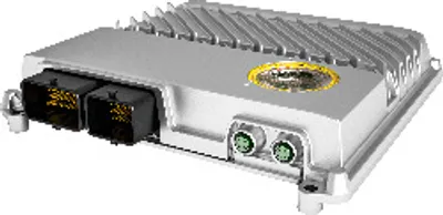 Available on requestB&R X90CP154.60-S1M – Interfaces, 1x Ethernet/POWERLINK (switchable)
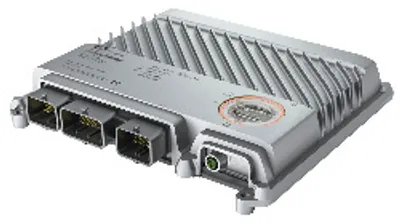 Available on requestB&R X90CP172.24-00 – Interfaces, 1x Ethernet, 1x USB, 3x CAN bus
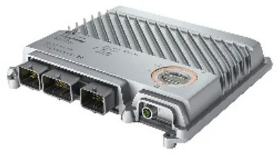 Available on requestB&R X90CP172.48-00 – Interfaces, 1x Ethernet, 1x USB, 3x CAN bus
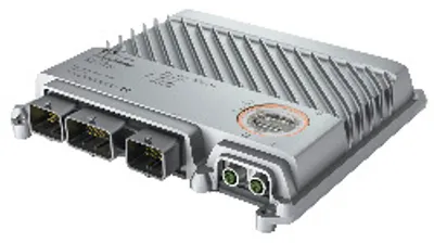 Available on requestB&R X90CP174.24-00 – Interfaces, 1x Ethernet, 1x USB, 3x CAN bus, 1x POWERLINK
 Available on requestB&R X90CP174.48-S1 – Interfaces, 1x Ethernet, 1x USB, 3x CAN bus, 1x POWERLINK
 Available on requestB&R X90DI110.10-00 – I/O module, 10 digital inputs 9 to 32 VDC for 1-wire…
 Available on requestB&R X90DSI00.04-00 – I/O module, IO-Link master with 4 IO-Link interfaces
 Available on requestB&R X90IF720.04-00 – Communication module, 3x CAN bus, 1x RS232