
B&R X90CP154.60-00M – Interfaces, 1x Ethernet/POWERLINK (switchable)
Request a Quote



Quick facts
| Availability | Confirmed on request |
| Category | X90 mobile control |
| Lifecycle | Active |
| Warranty | 12-month (new) · 3-month (used/refurbished) |
| Weight | 0.17 kg |
Shipping & availability
When can X90CP154.60-00M be shipped?
X90CP154.60-00M is sourced on request — request a quote and we'll confirm the exact availability and shipping timeline for this specific unit.
Can I pick up X90CP154.60-00M in person?
Local pickup from our Groningen, Netherlands warehouse may be possible — contact us before ordering to check availability and arrange a collection time.
Is express delivery available?
Yes — mention it when you request a quote for X90CP154.60-00M and we'll include express shipping options in our reply.
My factory is down and I need this urgently — can you help?
For a critical breakdown, contact us directly at +31 (0)50-7110348 or sales@partnerplc.com — we can look into same-day courier or dedicated taxi/hotshot delivery for X90CP154.60-00M, subject to availability and destination.
X90 mobile controller, ARM Cortex A9-650, 256 MB DDR3 RAM, 32 kB FRAM, 4 GB flash memory, 1 POWERLINK to M12, 1 Ethernet 10/100BASE-T to M12, 3 CAN on CMC header, 1 LIN on CMC header, 1 RS232 on CMC header, 60 multifunction I/O, 1 sensor power supply, die-cast aluminum housing, service access window, LED status indicators DNV certification
Accessories
Optional accessories (3)
| X90AC-BB.15-00 | BreakOut Box — X90 mobile 150, breakout box for development and testing |
| X90TB150.02-00 | CMC connector — X90 mobile 150, connector set for CMC header, with connector contacts and dummy plugs |
| X90CA150.02-00 | Wire harness — X90 mobile 150, wiring harness starter set for X90CP15x, 2 m, for CMC header |
Specifications
Short description
| Interfaces | 1x Ethernet/POWERLINK (switchable), 1x POWERLINK, 3x CAN bus, 1x LIN bus, 1x RS232, 1x USB |
| System module | Controller |
General information
| Diagnostics – Module run/error | Yes, using LED status indicator, software and diagnostic output |
| Diagnostics – CPU function | Yes, using LED status indicator |
| Diagnostics – Ethernet | Yes, using LED status indicator |
| Support – Controller redundancy | No |
| Support – Storage health data support | Yes |
| Support – ACOPOS support | Yes |
| Support – reACTION-capable I/O channels | No |
| Support – Visual Components support | Yes |
| Certifications – CE | Yes |
| Certifications – UKCA | Yes |
| Certifications – CRA (Cyber Resilience Act) | In preparation |
| Certifications – DNV | Temperature: D (-25 to 55°C) ; Humidity: B (up to 100%) ; Vibration: B (4 g) ; EMC: B (bridge and open deck) ; Enclosure: B (engine room) |
| Insulation voltage for GND and housing | 500 V eff " data-placement="top" data-html="true" data-container="body" data-content="Connected to capacitors and 60 V VDR protective element."> |
| B&R ID code | 0x352C |
| Cooling | Fanless |
| Status indicators | Controller function, operating mode, overtemperature, Ethernet, POWERLINK |
| Power consumption " data-placement="top" data-html="true" data-container="body" data-content="Without USB"> | CPU at U e = 9 / 32 V: 4.8 / 6.0 W |
Input power supply
| Input voltage V_CPU, V_I/O " data-placement="top" data-html="true" data-container="body" data-content="Always connect V_CPU and V_I/O to a common voltage source. Supplying from different voltage sources is not permitted."> – Nominal voltage 12 V | 9 to 16 VDC |
| Input voltage V_CPU, V_I/O " data-placement="top" data-html="true" data-container="body" data-content="Always connect V_CPU and V_I/O to a common voltage source. Supplying from different voltage sources is not permitted."> – Nominal voltage 24 V | 16 to 32 VDC |
| Input current – V_CPU | During operation ; Typ. 420 mA at 12 V; Typ. 240 mA at 24 V; In standby mode ; Typ. 18 mA at 12 V ; Typ. 13 mA at 24 V |
| Input current – V_I/O | Max. 10 A per connection pin |
| Integrated protective function – V_CPU | No, required fuse 5 A slow-blow |
| Integrated protective function – V_I/O | No, required fuse 10 A slow-blow per connection pin |
| Input voltage | 9 to 32 VDC |
| Reset switching threshold | 5.4 V |
| Overvoltage " data-placement="top" data-html="true" data-container="body" data-content="Per ISO 15003:2019, tested for 5 minutes"> | Max. 48 V |
| Overvoltage protection | Load dump pulse A 202 V R i = 4 Ω " data-placement="top" data-html="true" data-container="body" data-content="V_CPU and V_I/O connected externally."> |
| Reverse polarity protection " data-placement="top" data-html="true" data-container="body" data-content="Per ISO 15003:2019, tested for 5 minutes"> | Max. -48 V |
Controller
| Processor – Data code | 32 kB |
| Processor – Program code | 32 kB |
| Processor – Type | ARM Cortex-A9 |
| Processor – Clock frequency | 650 MHz |
| Processor – L2 cache | 512 kB |
| Standard memory – RAM | 256 MB DDR3 SDRAM |
| Application memory – Guaranteed | 100 TB |
| Application memory – Results for 5 years | 54.8 GB/day |
| Application memory – Type | 4 GB flash memory |
| Application memory – Data retention | 10 years |
| Application memory – Guaranteed erase/write cycles | 100,000 |
| Application memory – Error-correcting code (ECC) | Yes |
| Real-time clock | Resolution 1 s, retention min. 48 hours, typ. 250 hours at 25°C, precision ±30 ppm over the entire temperature range |
| Floating point unit (FPU) | Yes |
| Integrated I/O processor | Processes I/O data points in the background |
| Option boards | Not available |
| Remanent variables | 32 kB FRAM, retention >10 years " data-placement="top" data-html="true" data-container="body" data-content="Configurable in Automation Studio."> |
| Shortest task class cycle time | 400 µs |
Interfaces
| Interface IF1 – Type | RS232 |
| Interface IF1 – Variant | Connection on CMC header X1.A |
| Interface IF1 – Max. distance | 3 m |
| Interface IF1 – Transfer rate | Max. 115.2 kbit/s |
| Interface IF2 – Physical layer | 10BASE-T/100BASE-TX |
| Interface IF2 – Half-duplex | Yes |
| Interface IF2 – Full-duplex | Yes |
| Interface IF2 – Autonegotiation | Yes |
| Interface IF2 – Auto-MDI/MDIX | Yes |
| Interface IF2 – Type | Ethernet / POWERLINK " data-placement="top" data-html="true" data-container="body" data-content="For daisy-chain wiring of multiple controllers, interface IF2 can be defined in Automation Studio as a POWERLINK hub in parallel with interface IF3."> |
| Interface IF2 – Variant | M12, D-coded |
| Interface IF2 – Line length | Max. 100 m between 2 stations (segment length) |
| Interface IF2 – Transfer rate | 10/100 Mbit/s |
| Interface IF3 – Physical layer | 100BASE-TX |
| Interface IF3 – Half-duplex | Yes |
| Interface IF3 – Full-duplex | No |
| Interface IF3 – Autonegotiation | Yes |
| Interface IF3 – Auto-MDI/MDIX | Yes |
| Interface IF3 – Fieldbus | POWERLINK managing or controlled node " data-placement="top" data-html="true" data-container="body" data-content="For daisy-chain wiring of multiple controllers, interface IF2 can be defined in Automation Studio as a POWERLINK hub in parallel with interface IF3."> |
| Interface IF3 – Type | Type 6 " data-placement="top" data-html="true" data-container="body" data-content="For additional information, see section "Communication / POWERLINK / General information / Hardware - IF/LS" in Automation Help."> |
| Interface IF3 – Variant | M12, D-coded |
| Interface IF3 – Line length | Max. 100 m between 2 stations (segment length) |
| Interface IF3 – Transfer rate | 100 Mbit/s |
| Interface IF4 – Type | USB 1.1/2.0 |
| Interface IF4 – Variant | Type A (under service access window) |
| Interface IF4 – Max. output current | 500 mA |
| Interface IF5 – Type | LIN |
| Interface IF5 – Variant | Connection on CMC header X1.A |
| Interface IF5 – Max. distance | 40 m |
| Interface IF5 – Transfer rate | Max. 19.2 kbit/s |
| Interface IF7 – Connection designation | CAN1 |
| Interface IF7 – Type | CAN bus |
| Interface IF7 – Variant | Connection on CMC header X1.A |
| Interface IF7 – Max. distance | 1000 m |
| Interface IF7 – Transfer rate | Max. 1 Mbit/s |
| Interface IF7 – Terminating resistor | External 120 Ω must be provided. |
| Interface IF8 – Connection designation | CAN2 |
| Interface IF8 – Type | CAN bus |
| Interface IF8 – Variant | Connection on CMC header X1.A |
| Interface IF8 – Max. distance | 1000 m |
| Interface IF8 – Transfer rate | Max. 1 Mbit/s |
| Interface IF8 – Terminating resistor | External 120 Ω must be provided. |
| Interface IF9 – Connection designation | CAN3 |
| Interface IF9 – Type | CAN bus |
| Interface IF9 – Variant | Connection on CMC header X1.A |
| Interface IF9 – Max. distance | 1000 m |
| Interface IF9 – Transfer rate | Max. 1 Mbit/s |
| Interface IF9 – Terminating resistor | External 120 Ω must be provided. |
Multi-function inputs
| Multifunction digital inputs MF-DI (std) – Quantity | 2 |
| Multifunction digital inputs MF-DI (std) – Function | Digital input ; Sink/Source circuit - Configurable per channel, configurable software input filter |
| Multifunction digital inputs MF-DI (CI) – Quantity | 8 |
| Multifunction digital inputs MF-DI (CI) – Function | Digital input ; Sink/Source circuit - Configurable per channel, configurable software input filter, counter function up to 50 kHz counter frequency (max. 4x AB, max. 2x ABR, max. 2x DF, max. 8x edge counter), edge detection with timestamp (for period duration, gate time measurement, differential time measurement) |
| Multifunction analog inputs MF-AI (std) – Quantity | 4 |
| Multifunction analog inputs MF-AI (std) – Function | Digital input ; Sink/Source circuit - Configurable per channel, configurable software input filter, fixed or ratiometrically configurable switching threshold. ; Analog input ; Measurement range 0 to 10 V / 0 to 32 V / 0/4 to 20 mA, configurable analog filter, configurable ramp limit, configurable threshold values, integrated input protection |
| Multifunction analog inputs MF-AI (AT) – Quantity | 8 |
| Multifunction analog inputs MF-AI (AT) – Function | Digital input (without diagnostics) ; Sink/Source circuit - Configurable per channel, configurable software input filter, fixed or ratiometrically configurable switching threshold. ; Digital input (with diagnostics) ; Configurable software input filter, open-circuit and short-circuit detection. ; Analog input ; Measurement range 0 to 10 V / 0 to 32 V / 0/4 to 20 mA / 0 to 4000 Ω / temperature inputs (Pt1000 characteristic curve), configurable analog filter, configurable ramp limit, configurable threshold values, integrated input protection |
| Multifunction analog inputs MF-AI (PVG) – Quantity | 8 |
| Multifunction analog inputs MF-AI (PVG) – Function | Digital input (without diagnostics) ; Sink/Source circuit - Configurable per channel, configurable software input filter, fixed or ratiometrically configurable switching threshold.; Digital input (with diagnostics) ; Configurable software input filter, open-circuit and short-circuit detection.; Analog input ; Measurement range 0 to 10 V / 0 to 32 V / 0/4 to 20 mA / 0 to 4000 Ω / temperature inputs (Pt1000 characteristic curve), configurable analog filter, configurable ramp limit, configurable threshold values, integrated input protection ; Ratiometric analog output (smoothed PWM signal) ; Short-circuit current 5.5 mA max. at 24 V, PWM frequency 25 kHz; PVG ; Short-circuit current 5.5 mA max. at 24 V, PVG frequency 25 kHz. |
Multi-function outputs
| Multifunction digital outputs (MF-DO) – Quantity | 8 |
| Multifunction digital outputs (MF-DO) – Functions | Digital output: ; 4 A nominal current, source circuit, integrated output protection per channel, configurable overload monitoring per channel, central cutoff via relay, parallel connection, current measurement, error state with configurable error filter.; Digital input: ; Sink/Source circuit configurable per channel, configurable software input filter |
| Multifunction PWM outputs MF-PWM (std) – Quantity | 16 |
| Multifunction PWM outputs MF-PWM (std) – Function | Digital output ; 4 A nominal current, source circuit, integrated output protection per channel, configurable overload monitoring per channel, central cutoff via relay,parallel connection, current measurement, error state with configurable error filter. ; PWM output ; 4 A nominal current, PWM frequency 15 Hz to 1 kHz, source circuit, integrated output protection per channel, configurable overload monitoring per channel, central cutoff via relay, parallel connection, current measurement, configurable switching edge shift to avoid load peaks, dither. ; Digital input ; Sink/Source circuit configurable per channel, configurable software input filter |
| Multifunction PWM outputs MF-PWM (bridge) – Quantity | 6 |
| Multifunction PWM outputs MF-PWM (bridge) – Function | Digital output ; 6 A nominal current, push-pull circuit, integrated output protection per channel, configurable overload monitoring per channel, central cutoff via relay,parallel connection, current measurement, error state with configurable error filter.; PWM output ; 6 A nominal current, PWM frequency 15 Hz to 4 kHz, 8 kHz in full-bridge mode, push-pull circuit, integrated output protection per channel, configurable overload monitoring per channel, central cutoff via relay, parallel connection, current measurement, configurable load current distribution of the PWM outputs, dither. ; Digital input ; Sink/Source circuit configurable per channel, configurable software input filter |
Digital inputs
| Input filter – Hardware | MF-DI: 3 µs; MF-AI (all): 300 µs; MF-DO: 150 µs; MF-PWM (bridge): 200 µs; MF-PWM (std): 150 µs " data-placement="top" data-html="true" data-container="body" data-content="At switching threshold = 50% supply voltage"> |
| Input filter – Software | Default 1 ms, configurable between 0 and 25 ms in 0.1 ms increments |
| Quantity | 8 to 60, depends on the use of multifunction inputs/outputs |
| Nominal voltage | 12 / 24 VDC |
| Input voltage | 9 to 32 VDC |
| Input current at 24 VDC | MF-DI (CI + std): Typ. 1.1 / 2.5 mA, configurable ; MF-AI (AT + PVG): Typ. 1.1 / 5.3 mA, configurable ; MF-AI (std): Typ. 1.1 mA ; MF-DO (std): Typ. 2.5 mA ; MF-PWM (all): Typ. 2.5 mA " data-placement="top" data-html="true" data-container="body" data-content="Input current for MF-DI and MF-AI corresponds to the selected input resistance."> |
| Input circuit | Sink/Source, configurable |
| Input resistance | MF-DI (CI + std): Typ. 9.15 / 20.2 kΩ, configurable ; MF-AI (AT + PVG): Typ. 4.42 / 22.1 kΩ, configurable ; MF-AI (std): Typ. 22 kΩ ; MF-DO (std): Typ. 9.15 kΩ ; MF-PWM (all): Typ. 9.15 kΩ |
| Input frequency | MF-DI: Max. 50 kHz |
| Switching threshold | MF-DI: 50% of supply voltage; MF-AI (all): Switching threshold and hysteresis configurable with software; MF-DO: 40% supply voltage; MF-PWM (all): 40% supply voltage |
Analog inputs
| Output format – Data type | INT |
| Output format – Voltage | 0 to 10 V: INT 0x0000 - 0x7FFF / 1 LSB = 0x0008 = 2.441 mV ; 0 to 32 V: INT 0x0000 - 0x7FFF / 1 LSB = 0x0008 = 7.812 mV |
| Output format – Current | 0x0000 - 0x7FFF / 1 LSB = 0x0008 = 4.883 µA |
| Output format – Resistance | 0 to 4000, resolution 1 Ω " data-placement="top" data-html="true" data-container="body" data-content="The values measured in the lower part of the measurement range are inaccurate due to the hardware; measurements in this range should therefore be avoided."> |
| Output format – Temperature input | -200 to 850, resolution 0.1°C |
| Input impedance in signal range – Voltage | >100 kΩ |
| Input impedance in signal range – Current | - |
| Load – Voltage | - |
| Load – Current | 100 Ω |
| Max. error " data-placement="top" data-html="true" data-container="body" data-content="At 25°C."> – Gain | <1.5% " data-placement="top" data-html="true" data-container="body" data-content="Based on the current measured value."> |
| Max. error " data-placement="top" data-html="true" data-container="body" data-content="At 25°C."> – Offset | <1.5% " data-placement="top" data-html="true" data-container="body" data-content="Based on the 10 V or 32 V measurement range."> |
| Max. error " data-placement="top" data-html="true" data-container="body" data-content="At 25°C."> – Gain | <1.5% " data-placement="top" data-html="true" data-container="body" data-content="Based on the current measured value."> |
| Max. error " data-placement="top" data-html="true" data-container="body" data-content="At 25°C."> – Offset | <1.5% " data-placement="top" data-html="true" data-container="body" data-content="Based on the 20 mA measurement range."> |
| Max. error " data-placement="top" data-html="true" data-container="body" data-content="At 25°C."> – Resistance | <5% " data-placement="top" data-html="true" data-container="body" data-content="Based on the 4 kΩ measurement range."> |
| Max. error " data-placement="top" data-html="true" data-container="body" data-content="At 25°C."> – Temperature input | <5% " data-placement="top" data-html="true" data-container="body" data-content="Based on the maximum measurement range (-200 to 850°C)."> |
| Max. gain drift – Voltage | <0.03%/°C " data-placement="top" data-html="true" data-container="body" data-content="Based on the current measured value."> |
| Max. gain drift – Current | <0.04%/°C " data-placement="top" data-html="true" data-container="body" data-content="Based on the current measured value."> |
| Max. gain drift – Resistance | <0.034%/°C " data-placement="top" data-html="true" data-container="body" data-content="Based on the current measured value."> |
| Max. gain drift – Temperature input | <0.024%/°C " data-placement="top" data-html="true" data-container="body" data-content="Based on the current measured value."> |
| Max. offset drift – Voltage | <0.06%/°C " data-placement="top" data-html="true" data-container="body" data-content="Based on the 10 V or 32 V measurement range."> |
| Max. offset drift – Current | <0.06%/°C " data-placement="top" data-html="true" data-container="body" data-content="Based on the 20 mA measurement range."> |
| Max. offset drift – Resistance | <0.018%/°C " data-placement="top" data-html="true" data-container="body" data-content="Based on the 4 kΩ measurement range."> |
| Max. offset drift – Temperature input | <0.027%/°C " data-placement="top" data-html="true" data-container="body" data-content="Based on the maximum measurement range (-200 to 850°C)."> |
| Quantity | 0 to 20, depends on the use of multifunction inputs |
| Input | 0 to 10 V / 0 to 32 V / 0/4 to 20 mA / 0 to 4000 Ω / Temperature inputs (Pt1000 characteristic curve) |
| Digital converter resolution | 12-bit |
| Conversion time | 160 μs |
| Measuring current resistance / Temperature input | <2.2 mA |
| Open-circuit detection | From the application |
| Conversion procedure | SAR |
| Input filter | First-order low-pass filter / cutoff frequency of voltage input 350 Hz, current input 200 Hz |
| Nonlinearity | <0.05% (resistance) ; <0.2% (temperature inputs) |
Sensor power supply
| Voltage | 5/10 V " data-placement="top" data-html="true" data-container="body" data-content="At 10 V sensor power supply, the V_CPU power supply must be ≥12 VDC."> |
| Current | Max. 400 mA ±3% |
Digital outputs
| Switching frequency – Resistive load | MF-DO: Max. 250 Hz |
| Switching frequency – Inductive load | MF-DO: Load current 4 A: Max. 4 mH (see section "Switching inductive loads") |
| Output voltage – Nominal | 9 to 32 VDC |
| Current measurement – Gain | MF-DO: <12%; MF-PWM (bridge): <0.5%; MF-PWM (std): <3% " data-placement="top" data-html="true" data-container="body" data-content="Based on the current measured value."> |
| Current measurement – Offset | MF-DO: <1% ; MF-PWM (bridge): <0.25%; MF-PWM (std): <1.5% " data-placement="top" data-html="true" data-container="body" data-content="Based on the 20 A measurement range."> |
| Current measurement – Current measurement range | MF-DO: 0 to 20 A; MF-PWM (bridge): ±10 A; MF-PWM (std): 0 to 10 A |
| Current measurement – Resolution | INT ; MF-DO: INT 0x0000 to 0x7FFF / 1 LSB = 610 µA ; MF-PWM (bridge): INT 0x8001 to 0x7FFF / 1 LSB = 305 μA ; MF-PWM (std): INT 0x0000 to 0x7FFF / 1 LSB = 305 μA |
| Current measurement – Max. gain drift | MF-DO: <0.2%/°C; MF-PWM (bridge): <0.04%/°C; MF-PWM (std): <0.2%/°C " data-placement="top" data-html="true" data-container="body" data-content="Based on the current measured value."> |
| Current measurement – Max. offset drift | MF-DO: <0.005%/°C; MF-PWM (all): <0.005%/°C " data-placement="top" data-html="true" data-container="body" data-content="Based on the 20 A measurement range."> |
| Quantity | 0 to 30, depends on the use of multifunction outputs |
| Variant | MF-DO: Current-sourcing sinking FET, channels can be connected in parallel in pairs.; MF-PWM (bridge): Current-sourcing/Current-sinking FET, channels can be connected in parallel.; MF-PWM (std): Current-sourcing sinking FET, channels can be connected in parallel in pairs. " data-placement="top" data-html="true" data-container="body" data-content="For additional information about the parallel connection, see section "Derating"."> |
| Nominal voltage | 12 / 24 VDC |
| Switching voltage | MF-DO, MF-PWM: V_IO -15%; MF-PVG, MF-AI (ratiometric output) : V_CPU - 15% |
| Digital converter resolution | 12-bit |
| Nominal output current | MF-DO: 4 A; MF-PWM (bridge): 6 A; MF-PWM (std): 4 A |
| Output protection | Thermal shutdown in the event of overcurrent or short circuit.; MF-PWM only (all): Integrated protection for switching inductive loads |
| Diagnostic status | Overload |
| Leakage current when the output is switched off | MF-DO: Typ. 10 μA, max. 4.1 mA; MF-PWM (bridge): Typ. 20 μA, max. 4.1 mA; MF-PWM (std): Typ. 10 μA, max. 4.1 mA |
| R DS(on) | MF-DO: <80 mΩ; MF-PWM (all): <50 mΩ |
| Residual voltage | <1 V at 4 A nominal current |
| Peak short-circuit current | MF-DO: 90 A; MF-PWM (bridge): 50 A; MF-PWM (std): 90 A |
| Braking voltage when switching off inductive loads | MF-DO: Typ. 64 VDC; MF-PWM (std): Typ. 64 VDC |
| Switching delay | MF-DO: Max. 150 μs; MF-PWM (all): Max. 150 μs |
| Sampling time | MF-DO: 160 μs; MF-PWM (bridge): 40 µs; MF-PWM (std): 80 μs |
PWM output
| Max. error at 25°C – Gain | MF-PWM (bridge): <0.5%; MF-PWM (std): <3% " data-placement="top" data-html="true" data-container="body" data-content="Based on the current measured value."> |
| Max. error at 25°C – Offset | MF-PWM (bridge): <0.25%; MF-PWM (std): <1.5% " data-placement="top" data-html="true" data-container="body" data-content="Based on the 20 A measurement range."> |
| Current measurement – Current measurement range | MF-PWM (bridge): ±10 A; MF-PWM (std): 10 A |
| Current measurement – Conversion time | MF-PWM (bridge): 40 μs; MF-PWM (std): 80 µs |
| Current measurement – Resolution | INT ; MF-PWM (bridge): INT 0x8001 to 0x7FFF / 1 LSB = 305 μA; MF-PWM (std): INT 0x0000 to 0x7FFF / 1 LSB = 305 μA |
| Quantity | MF-PWM (bridge): 0 to 6x 6 A ; MF-PWM (std): 0 to 16x 4 A ; Depends on the use of multifunction outputs |
| Nominal voltage | 12 / 24 VDC |
| Supply voltage (permissible range) | 9 to 32 VDC |
| Digital converter resolution | 12-bit |
| PWM frequency | MF-PWM (bridge): 15 Hz to 4 kHz; MF-PWM (std): 15 Hz to 1 kHz |
| Duty cycle | PWM (bridge): 0 to 32767 or -32767, min. resolution 160 ns depending on PWM frequency ; PWM (std): 0 to 32767, min. resolution 160 ns depending on PWM frequency |
| Max. gain drift | MF-PWM (bridge): <0.04%/°C; MF-PWM (std): <0.2%/°C " data-placement="top" data-html="true" data-container="body" data-content="Based on the current measured value."> |
| Max. offset drift | MF-PWM (all): <0.005%/°C " data-placement="top" data-html="true" data-container="body" data-content="Based on the 20 A measurement range."> |
| Common mode error | MF-PWM (all): 0.01%/V " data-placement="top" data-html="true" data-container="body" data-content="Based on the 20 A measurement range."> |
| Output protection | Thermal shutdown in the event of overcurrent or short circuit, integrated protection for switching inductive loads |
| Variant | MF-PWM (bridge): Current-sourcing/Current-sinking FET, channels can be connected in parallel.; MF-PWM (std): Channels can be connected in parallel in pairs. " data-placement="top" data-html="true" data-container="body" data-content="For additional information about the parallel connection, see section "Derating"."> |
| Diagnostic status | Overload |
| Peak short-circuit current | 50 A (max. 0.2 ms) |
Status outputs
| Quantity | 1 |
| Variant | Connection A2 - Source |
| RDS(on) | 1.4 Ω |
| Max. continuous current | 20 mA |
Electrical properties
| Summation current – Complete system | Max. 30 A |
| Inrush current | Typ. 500 A for <300 µs |
| Electrical isolation | Ethernet (IF2) and POWERLINK (IF3) isolated from each other and from other interfaces |
Operating conditions
| Mounting orientation – Any | Yes |
| Installation elevation above sea level | Max. 4000 m |
| Degree of protection per EN 60529 | IP69K " data-placement="top" data-html="true" data-container="body" data-content="Applied only if mating connector (M12/CMC) connected or with M12 protective covers (0.6 Nm torque) and closed service access window."> |
Ambient conditions
| Temperature – Horizontal mounting orientation | -40 to 85°C housing surface |
| Temperature – Vertical mounting orientation | -40 to 85°C housing surface |
| Temperature – Derating | See section "Derating". |
| Temperature – Storage | -40 to 85°C |
| Temperature – Transport | -40 to 85°C |
| Relative humidity – Operation | 5 to 100%, condensing |
| Relative humidity – Storage | 5 to 95%, non-condensing |
| Relative humidity – Transport | 5 to 95%, non-condensing |
Mechanical properties
| Dimensions – Width | 225 mm |
| Dimensions – Length | 219.5 mm |
| Dimensions – Height | 43.5 mm |
| Weight | Max. 1740 g |
Brief overview
| Content of delivery | 2x protective covers for unused female M12 connectors |
Downloads & documentation
Official documents from B&R, downloaded directly from the manufacturer.
Data sheets & manuals
| Data sheet X90CP154.xx-00 | PDF · 11 MB · 1.17 (07/09/2025) - EN |
| Open Source Licenses X90CPxxxx | ZIP · 1 MB · 1.00 (09/05/2024) |
| V4.12 CP Upgrade (CpLin) RevInfo | PDF · 57 KB · 1.01.0.0 (06/13/2024) - EN |
| V4.12 Library Upgrade (CpLin) RevInfo | PDF · 50 KB · 1.01.1.0 (08/08/2024) - EN |
| V6.0 CP Upgrade (CpLin) RevInfo | PDF · 57 KB · 1.1.0.0 (06/13/2024) - EN |
| V6.0 Library Upgrade (CpLin) RevInfo | PDF · 50 KB · 1.1.1.0 (08/08/2024) - EN |
| X90 mobile System User´s Manual | PDF · 27 MB · 2.40 (02/03/2026) - EN |
| X90CP15x pin allocation CMC connector | ZIP · 872 KB · 1.00 (07/16/2024) |
CAD & dimension drawings
| 3D File STEP X90CP15x.xx-xx | ZIP · 2 MB · 1.00 (07/17/2024) |
Certificates (2)
| EU Data Act - X90 - Connected Product Information Notice | PDF · 92 KB · 1.00 (09/30/2025) |
| TAA00003GX DNV Type Approval Certificate X90 | PDF · 176 KB · 1.00 R1 (05/04/2026) |
More B&R parts
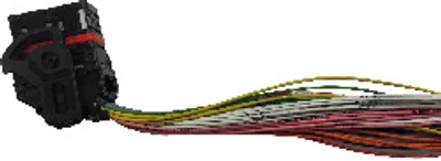 Available on requestB&R X90CA124.02-00 – Accessories, wiring harness with mating connector X1
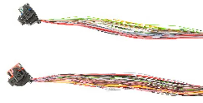 Available on requestB&R X90CA150.02-00 – Accessories, set consisting of 2x wiring harness with 1x…
 Available on requestB&R X90CM480.04-00 – I/O module, X90 mobile 4-channel analog input module for…
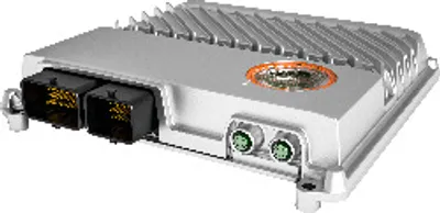 Available on requestB&R X90CP154.60-00 – Interfaces, 1x Ethernet/POWERLINK (switchable)
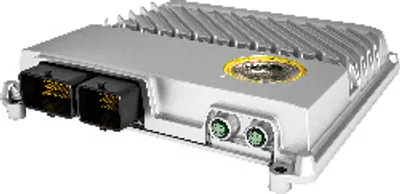 Available on requestB&R X90CP154.60-S1 – Interfaces, 1x Ethernet/POWERLINK (switchable)
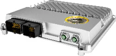 Available on requestB&R X90CP154.60-S1M – Interfaces, 1x Ethernet/POWERLINK (switchable)
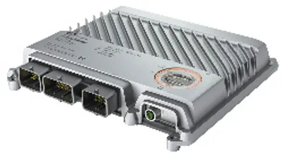 Available on requestB&R X90CP172.24-00 – Interfaces, 1x Ethernet, 1x USB, 3x CAN bus
 Available on requestB&R X90CP172.48-00 – Interfaces, 1x Ethernet, 1x USB, 3x CAN bus