
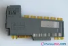
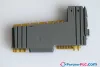

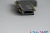
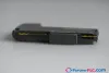
B&R X20AO2632 New without box Rev. A0
Request a Quote



Quick facts
| Availability | In stock — 1 available |
| Category | Analog I/O Modules |
| Warranty | 12-month |
| Weight | 0.018 kg |
| Country of origin | AT |
| Datasheet | Manufacturer datasheet ↗ |
Shipping & availability
When can X20AO2632 be shipped?
X20AO2632 is in stock and typically ships within 1 business day via UPS, DHL or FedEx, worldwide.
Can I pick up X20AO2632 in person?
Local pickup from our Groningen, Netherlands warehouse may be possible — contact us before ordering to check availability and arrange a collection time.
Is express delivery available?
Yes — alongside standard UPS, DHL and FedEx shipping, express (next-day) delivery is available at checkout for in-stock items like X20AO2632.
My factory is down and I need this urgently — can you help?
For a critical breakdown, contact us directly at +31 (0)50-7110348 or sales@partnerplc.com — we can look into same-day courier or dedicated taxi/hotshot delivery for X20AO2632, subject to availability and destination.
• 2 analog outputs
• Either current or voltage signal possible
• 16-bit digital converter resolution
• NetTime timestamp: Switch-off time
The module is equipped with 2 outputs with 16-bit (including sign) digital converter resolution. It is possible to select between the current and voltage signal using different terminals.
This module is designed for X20 6-pin terminal blocks. If needed (e.g. for logistical reasons), the 12-pin terminal block can also be used.
NetTime timestamp for output
For many applications, not only the output value is important, but also the exact switching time. The module is equipped with a NetTime timestamp function for this that can define a switching time to the nearest microsecond.
The timestamp function is based on synchronized timers. The CPU can predefine output events and provide them with a timestamp. After transferring the respective data, including the exact time, the module executes the predefined action at the exactly defined time.
Accessories
Required accessories (order separately)
| X20BM15 | Bus modules — The bus module is the base for all X20 24 VDC I/O modules; The internal I/O supply is interconnected; Manual node number assignment; Indepe… |
| X20BM11 | Bus modules — Bus module for 24 VDC I/O modules; The internal I/O power supply is connected through. The bus module is the base for all 24 VDC I/O module… |
| X20TB12 | Terminal blocks — Tool-free wiring with push-in technology; Simple wire release using lever; Ability to label each terminal; Plain text labeling also possibl… |
| X20TB06 | Terminal blocks — Tool-free wiring with push-in technology; Simple wire release using lever; Ability to label each terminal; Plain text labeling also possibl… |
Specifications
Short description
| I/O module | 2 analog outputs ±10 V or 0 to 20 mA |
General information
| Diagnostics – Module run/error | Yes, using LED status indicator and software |
| Diagnostics – Channel type | Yes, using software |
| Power consumption – Bus | 0.01 W |
| Power consumption – Internal I/O | 1.1 W |
| Certifications – CE | Yes |
| Certifications – UKCA | Yes |
| Certifications – CRA (Cyber Resilience Act) | In preparation |
| Certifications – ATEX | Zone 2, II 3G Ex nA nC IIA T5 Gc; IP20, Ta (see X20 user's manual); FTZÚ 09 ATEX 0083X |
| Certifications – UL | cULus E115267; Industrial control equipment |
| Certifications – HazLoc | cCSAus 244665; Process control equipment; for hazardous locations; Class I, Division 2, Groups ABCD, T5 |
| Certifications – DNV | Temperature: B (0 to 55°C); Humidity: B (up to 100%); Vibration: B (4 g); EMC: B (bridge and open deck) |
| Certifications – CCS | Yes |
| Certifications – LR | ENV1 |
| Certifications – KR | Yes |
| Certifications – ABS | Yes |
| Certifications – BV | EC33B ; Temperature: 5 - 55°C; Vibration: 4 g; EMC: Bridge and open deck |
| Certifications – KC | Yes |
| B&R ID code | 0x1BA4 |
| Status indicators | I/O function per channel, operating state, module status |
| Additional power dissipation caused by actuators (resistive) [W] | - |
Analog outputs
| Digital converter resolution – Voltage | ±15-bit |
| Digital converter resolution – Current | 15-bit |
| Max. error " data-placement="top" data-html="true" data-container="body" data-content="At 25°C"> – Gain | ±0.045% " data-placement="top" data-html="true" data-container="body" data-content="Based on the current output value."> |
| Max. error " data-placement="top" data-html="true" data-container="body" data-content="At 25°C"> – Offset | ±0.025% " data-placement="top" data-html="true" data-container="body" data-content="Based on the entire output range."> |
| Max. error " data-placement="top" data-html="true" data-container="body" data-content="At 25°C"> – Gain | ±0.09% " data-placement="top" data-html="true" data-container="body" data-content="Based on the current output value."> |
| Max. error " data-placement="top" data-html="true" data-container="body" data-content="At 25°C"> – Offset | ±0.045% " data-placement="top" data-html="true" data-container="body" data-content="Based on the entire output range."> |
| Output format – Voltage | INT 0x8000 - 0x7FFF / 1 LSB = 0x0001 = 305.176 µV |
| Output format – Current | INT 0x0000 - 0x7FFF / 1 LSB = 0x0001 = 610.352 nA |
| Load per channel – Voltage | Max. ±10 mA, load ≥1 kΩ |
| Load per channel – Current | Load max. 600 Ω (Rev. ≥ J0), 500 Ω (Rev. < J0) |
| Max. gain drift – Voltage | ±0.015%/°C " data-placement="top" data-html="true" data-container="body" data-content="Based on the current output value."> |
| Max. gain drift – Current | ±0.02%/°C " data-placement="top" data-html="true" data-container="body" data-content="Based on the current output value."> |
| Max. offset drift – Voltage | ±0.013 %/°C " data-placement="top" data-html="true" data-container="body" data-content="Based on the entire output range."> |
| Max. offset drift – Current | ±0.013 %/°C " data-placement="top" data-html="true" data-container="body" data-content="Based on the entire output range."> |
| Error caused by load change – Voltage | Max. 0.11%, from 10 MΩ → 1 kΩ, resistive |
| Error caused by load change – Current | Max. 0.5%, from 1 Ω → 600 Ω, resistive |
| Output | ±10 V or 0 to 20 mA, via different terminal connections |
| Conversion time | 50 µs for all outputs |
| Settling time on output change over entire range | 500 μs (Rev. <H0: 1 ms) |
| Switch on/off behavior | Internal enable relay for startup |
| Output protection | Short-circuit proof |
| Short-circuit proof | Current limiting ±40 mA |
| Output filter | First-order low-pass filter / cutoff frequency 10 kHz |
| Nonlinearity | <0.007% " data-placement="top" data-html="true" data-container="body" data-content="Based on the entire output range."> |
| Insulation voltage between channel and bus | 500 V eff |
Electrical properties
| Electrical isolation | Channel isolated from bus; Channel not isolated from channel |
Operating conditions
| Mounting orientation – Horizontal | Yes |
| Mounting orientation – Vertical | Yes |
| Installation elevation above sea level – 0 to 2000 m | No limitation |
| Installation elevation above sea level – >2000 m | Reduction of ambient temperature by 0.5°C per 100 m |
| Degree of protection per EN 60529 | IP20 |
Ambient conditions
| Temperature – Horizontal mounting orientation | -25 to 60°C |
| Temperature – Vertical mounting orientation | -25 to 50°C |
| Temperature – Derating | - |
| Temperature – Storage | -40 to 85°C |
| Temperature – Transport | -40 to 85°C |
| Relative humidity – Operation | 5 to 95%, non-condensing |
| Relative humidity – Storage | 5 to 95%, non-condensing |
| Relative humidity – Transport | 5 to 95%, non-condensing |
Mechanical properties
| Note | Order 1x terminal block X20TB06 or X20TB12 separately. ; Order 1x bus module X20BM11 separately. |
| Pitch | 12.5 +0.2 mm |
Downloads & documentation
Official documents from B&R, downloaded directly from the manufacturer.
Data sheets & manuals
| Datasheet X20AO2632 | PDF · 865 KB · 3.30 (05/26/2025) - EN |
| X20 Package leaflet ATEX/CSA | PDF · 2 MB · 1.4 (09/17/2024) |
| X20 System User´s Manual | PDF · 50 MB · 4.40 (03/10/2026) - EN |
CAD & dimension drawings
| 3D File DXF/STEP X20 Electronic module | ZIP · 10 KB · 1.0 (10/17/2005) |
| 3D File STEP X20 I/O-Slice | ZIP · 872 KB · 1.1 (03/13/2019) |
| Dimensions PDF X20 Electronic module | PDF · 3 KB · 1.0 (10/17/2005) |
Certificates (16)
More B&R parts
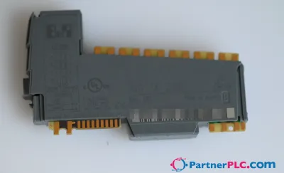 NewB&R X20DC2396 New without box Rev. G0 – 2 ABR incremental encoder 24 V
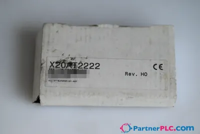 NewB&R X20AT2222 New Rev. H0 – 2 inputs for resistance temperature measurement
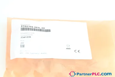 NewB&R 8TB2104.203L-00 New without box – 4-pin screw clamp terminal block, 1-row, pitch: 5.08 mm
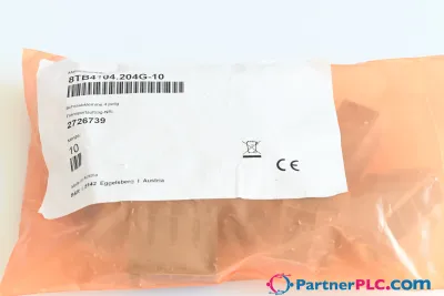 NewB&R 8TB4104.204G-10 New without box – 4-pin screw clamp terminal block, 1-row, pitch: 10.16 mm
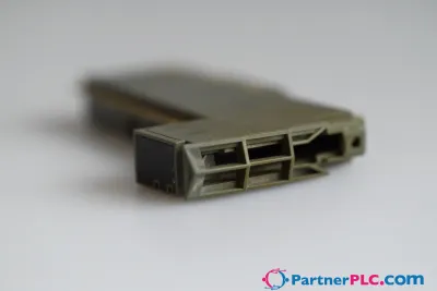 UsedB&R X20CS1070 Used Rev. E0 – CAN bus interface for serial
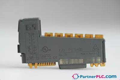 UsedB&R X20PS9400 Used Rev. D0 – Supply for the bus controller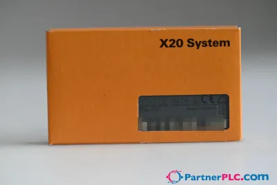
 NewB&R 8TB3104.204G-11 New without box – 4-pin screw clamp terminal block, 1-row, pitch: 7.62 mm