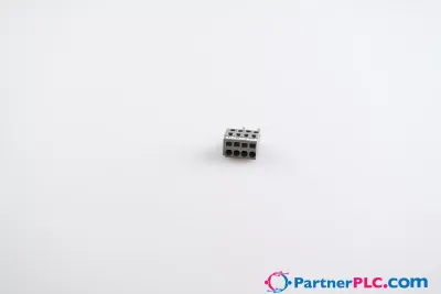
Control Signal Terminal Strip; E.ON Version; according to § 14a EnWG
Request a Quote



Quick facts
| Availability | Confirmed on request |
| Category | Rail-Mount Terminal Blocks |
| Lifecycle | active |
| Warranty | 12-month (new) · 3-month (used/refurbished) |
Shipping & availability
When can 821-500 be shipped?
821-500 is sourced on request — request a quote and we'll confirm the exact availability and shipping timeline for this specific unit.
Can I pick up 821-500 in person?
Local pickup from our Groningen, Netherlands warehouse may be possible — contact us before ordering to check availability and arrange a collection time.
Is express delivery available?
Yes — mention it when you request a quote for 821-500 and we'll include express shipping options in our reply.
My factory is down and I need this urgently — can you help?
For a critical breakdown, contact us directly at +31 (0)50-7110348 or sales@partnerplc.com — we can look into same-day courier or dedicated taxi/hotshot delivery for 821-500, subject to availability and destination.
<p><b>Control Signal Terminal Strips per § 14a EnWG</b></p><p> </p><p>Due to the Energy Industry Act (EnWG), system operators whose connection power is greater than 4.2 kW (usually wallboxes or heat pumps for private households) are obligated to install throttle devices that can be controlled by the grid operator in an emergency to ensure grid stability in the event of excessive power consumption. For this purpose, WAGO offers the Control Signal Terminal Strips according to § 14a EnWG as an interface between consumers and grid operators, which were developed in cooperation with grid operators according to the valid TABs. They offer the advantages of a uniform structure, standards and meet the requirements for clear separation of load and control current.</p><p>These sets are delivered ready for installation and without a DIN-rail for the end user. They are developed for the German energy market.</p>
Specifications
Notes
| Note | Set will be delivered without DIN-rail. |
Electrical data - Ratings per IEC/EN
| Ratings per | IEC/EN 60947-7-1 |
| Nominal voltage (III/3) | 800 V |
| Rated impulse withstand voltage (III / 3) | 8 kV |
| Rated current | 24 A |
| Legend (ratings) | (III / 3) ≙ Overvoltage category III / Pollution degree 3 |
Electrical data - Ratings per UL
| Approvals per | UL 1059 |
| Rated voltage UL (Use Group B) | 600 V |
| Rated current UL (Use Group B) | 20 A |
| Rated voltage UL (Use Group C) | 600 V |
| Rated current UL (Use Group C) | 20 A |
Electrical data - Ratings per CSA
| Approvals per | CSA 22.2 No 158 |
| Rated voltage CSA (Use Group B) | 600 V |
| Rated current CSA (Use Group B) | 20 A |
| Rated voltage CSA (Use Group C) | 600 V |
| Rated current CSA (Use Group C) | 20 A |
Electrical data - Ex information
| Reference to hazardous areas | See “Downloads – Documentation – Additional Information: Technical Section; Technical Explications” |
| Ratings per | ATEX: PTB 18 ATEX 1005 U / IECEx: PTB 18.0012U (Ex eb IIC Gb) |
| Rated voltage EN (Ex e II) | 550 V |
| Rated current (Ex e II) | 22 A |
| Rated current (Ex e II) with jumper | 20 A |
Electrical data - Power Loss
| Power loss, per pole (potential) | 0.766 W |
| Rated current I<sub>N</sub> for power loss specification | 24 A |
| Resistance value for specified, current-dependent power loss | 0.001 Ω |
Electrical data - General information
| Wiring direction | Front-entry wiring |
Connection data
| Clamping units | 16 |
| Total number of potentials | 8 |
| Number of levels | 1 |
| Number of jumper slots | 16 |
Connection data - Connection 1
| Connection technology | Push-in CAGE CLAMP® |
| Actuation type | Push-button |
| Connectable conductor materials | Copper |
| Nominal cross-section | 2.5 mm² |
| Solid conductor | 0.25 … 4 mm² / 18 … 12 AWG |
| Solid conductor; push-in termination | 0.75 … 4 mm² / 18 … 12 AWG |
| Fine-stranded conductor | 0.25 … 4 mm² / 22 … 12 AWG |
| Fine-stranded conductor; with insulated ferrule | 0.25 … 2.5 mm² / 22 … 14 AWG |
| Fine-stranded conductor; with ferrule; push-in termination | 1 … 2.5 mm² / 18 … 14 AWG |
| Note (conductor cross-section) | Depending on the conductor characteristic, a conductor with a smaller cross-section can also be inserted via push-in termination. |
| Strip length | 10 … 12 mm / 0.39 … 0.47 inches |
| Wiring direction | Front-entry wiring |
Physical data
| Width | 54.4 mm / 2.143 inches |
| Height | 48.5 mm / 1.909 inches |
| Depth from upper-edge of DIN-rail | 32.9 mm / 1.295 inches |
| Depth | 39.5 mm / 1.555 inches |
Mechanical data
| Mounting type | DIN-35 rail |
Material data
| Note (material data) | Information on material specifications can be found here |
| Material group | I |
| Insulation material (main housing) | Polyamide (PA66) |
| Flammability class per UL94 | V0 |
| Fire load | 1.272 MJ |
| Weight | 50.4 g |
Environmental requirements
| Processing temperature | -35 … +85 °C |
| Continuous operating temperature | -60 … +105 °C |
Commercial data
| PU (SPU) | 1 pcs |
| Packaging type | Box |
| Country of origin | DE |
| GTIN | 4066966654103 |
| Customs tariff number | 85369010000 |
Product Classification
| ETIM 9.0 | EC000897 |
| ETIM 10.0 | EC000897 |
| ECCN | NO US CLASSIFICATION |
Environmental Product Compliance
| RoHS Compliance Status | Compliant,No Exemption |