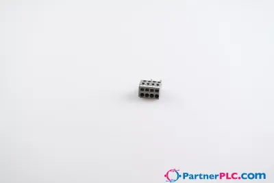
2-conductor PCB terminal block; 0.75 mm²; Pin spacing 10/10.16 mm; 16-pole; PUSH WIRE®; gray



Quick facts
| Availability | Confirmed on request |
| Category | PCB Terminal Blocks and Pluggable Connectors |
| Lifecycle | active |
| Warranty | 12-month (new) · 3-month (used/refurbished) |
Shipping & availability
When can 254-366 be shipped?
254-366 is sourced on request — request a quote and we'll confirm the exact availability and shipping timeline for this specific unit.
Can I pick up 254-366 in person?
Local pickup from our Groningen, Netherlands warehouse may be possible — contact us before ordering to check availability and arrange a collection time.
Is express delivery available?
Yes — mention it when you request a quote for 254-366 and we'll include express shipping options in our reply.
My factory is down and I need this urgently — can you help?
For a critical breakdown, contact us directly at +31 (0)50-7110348 or sales@partnerplc.com — we can look into same-day courier or dedicated taxi/hotshot delivery for 254-366, subject to availability and destination.
<h2>PCB terminal block, 254 Series, PUSH WIRE®</h2><br/><br/>This PCB terminal block (item number 254-366) is designed for quick and easy connections. It offers the flexibility needed for different mounting types. Ensure that the strip lengths are between 10 and 12 mm when connecting conductors to this PCB terminal block. This product features one conductor terminal and utilizes PUSH WIRE®. Our reliable PUSH WIRE® connection offers the fastest method for clamping conductors. It utilizes the conductor's stiffness to overcome the clamping spring's contact force. The dimensions are (161.5 x 20.5 x 13.5) mm (width x height x depth). Depending on the conductor type, this PCB terminal block is designed for conductor cross sections ranging from 0.25 mm² to 0.75 mm².<br/><br/><h3></h3><br/><br/>The contact surface is coated with tin. An operating tool is used to operate this PCB terminal block. THT is used to solder the PCB terminal block. The conductor is designed to be inserted into the board at an angle of 45°..<br/>
Specifications
Electrical data - Ratings per IEC/EN
| Ratings per | IEC/EN 60664-1 |
| Nominal voltage (III/3) | 630 V |
| Rated impulse withstand voltage (III / 3) | 8 kV |
| Rated voltage (III/2) | 1000 V |
| Rated impulse withstand voltage (III/2) | 8 kV |
| Nominal voltage (II/2) | 1000 V |
| Rated impulse withstand voltage (II/2) | 8 kV |
| Rated current | 10 A |
| Legend (ratings) | (III / 2) ≙ Overvoltage category III / Pollution degree 2 |
| Ratings per | IEC/EN 60664-1 / IEC/EN 60664-1 / IEC/EN 60664-1 |
| Overvoltage category | III / III / II |
| Pollution degree | 3 / 2 / 2 |
| Nominal voltage | 630 V / 1000 V / 1000 V |
| Rated impulse withstand voltage | 8 kV / 8 kV / 8 kV |
| Rated current | 10 A / 10 A / 10 A |
Electrical data - Ratings per UL
| Approvals per | UL 1059 |
| Rated voltage UL (Use Group B) | 300 V |
| Rated current UL (Use Group B) | 10 A |
| Rated voltage UL (Use Group D) | 300 V |
| Rated current UL (Use Group D) | 10 A |
| Approvals per | UL 1059 / UL 1059 / UL 1059 |
| Use group | B / C / D |
| Rated voltage | 300 V / 300 V |
| Rated current | 10 A / 10 A |
Electrical data - Ratings per CSA
| Approvals per | CSA |
| Rated voltage CSA (Use Group B) | 300 V |
| Rated current CSA (Use Group B) | 10 A |
| Rated voltage CSA (Use Group D) | 300 V |
| Rated current CSA (Use Group D) | 10 A |
| Approvals per | CSA / CSA / CSA |
| Use group | B / C / D |
| Rated voltage | 300 V / 300 V |
| Rated current | 10 A / 10 A |
Connection data
| Clamping units | 32 |
| Total number of potentials | 16 |
| Number of connection types | 1 |
| Number of levels | 1 |
Connection data - Connection 1
| Connection technology | PUSH WIRE® |
| Actuation type | Operating tool |
| Solid conductor | 0.25 … 0.75 mm² / 22 … 18 AWG |
| Strip length | 10 … 12 mm / 0.39 … 0.47 inches |
| Conductor connection direction to PCB | 45 ° |
| Pole number | 16 |
Physical data
| Pin spacing | 10/10.16 mm / 0.394/0.4 inches |
| Width | 161.5 mm / 6.358 inches |
| Height | 20.5 mm / 0.807 inches |
| Height from the surface | 16.5 mm / 0.65 inches |
| Depth | 13.5 mm / 0.531 inches |
| Solder pin length | 4 mm |
| Solder pin dimensions | 0.5 x 0.75 mm |
| Drilled hole diameter with tolerance | 1.1 (+0.1) mm |
PCB contact
| PCB contact | THT |
| Solder pin arrangement | over the entire terminal strip (in-line) |
| Number of solder pins per potential | 2 |
Material data
| Note (material data) | Information on material specifications can be found here |
| Color | gray |
| Material group | I |
| Insulation material (main housing) | Polyamide (PA66) |
| Flammability class per UL94 | V0 |
| Clamping spring material | Chrome-nickel spring steel (CrNi) |
| Contact material | Electrolytic copper (ECu) |
| Contact plating | Tin |
| Fire load | 0.533 MJ |
| Weight | 26.2 g |
Environmental requirements
| Limit temperature range | -60 … +105 °C |
Commercial data
| Product Group | 4 (Printed Circuit Connectors) |
| PU (SPU) | 20 (5) pcs |
| Packaging type | box |
| Country of origin | PL |
| GTIN | 4044918941983 |
| Customs tariff number | 85369010000 |
Product Classification
| UNSPSC | 39121409 |
| eCl@ss 10.0 | 27-44-04-01 |
| eCl@ss 9.0 | 27-44-04-01 |
| ETIM 9.0 | EC002643 |
| ETIM 10.0 | EC002643 |
| ECCN | NO US CLASSIFICATION |
Environmental Product Compliance
| RoHS Compliance Status | Compliant,No Exemption |